Microturbine exhaust heat augmentation system

a technology of exhaust heat and micro-turbines, which is applied in the direction of machines/engines, generators/motors, lighting and heating apparatus, etc., can solve the problems of inefficiency, difficult heat transfer, and at best, and achieve the effect of efficiently transferring heat and boosting the temperature of the recuperator/boiler

Inactive Publication Date: 2005-04-12
WELLS FARGO BANK NAT ASSOC
View PDF4 Cites 41 Cited by
  • Summary
  • Abstract
  • Description
  • Claims
  • Application Information

AI Technical Summary

Benefits of technology

A still further feature of this invention is to provide for a microturbine as described a by-pass system that boost the temperature of the recuperator/boiler so as to

Problems solved by technology

As mentioned above this by-pass system allows the use of a microturbine which was heretofore not practical since the available temperature for powering the chiller fluctuated.
Obviously, when

Method used


Image

  • Microturbine exhaust heat augmentation system
  • Microturbine exhaust heat augmentation system
  • Microturbine exhaust heat augmentation system

Examples


Embodiment Construction

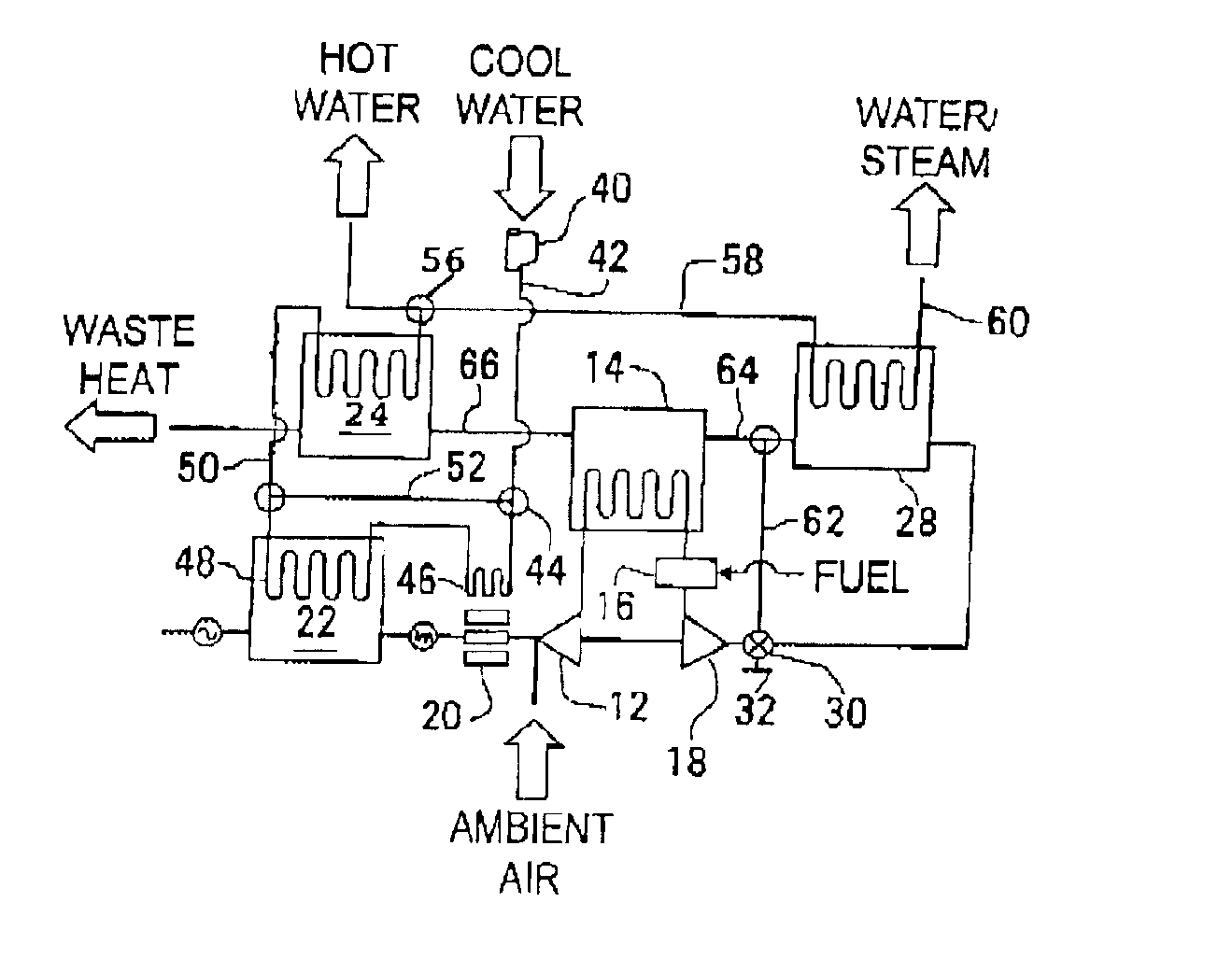
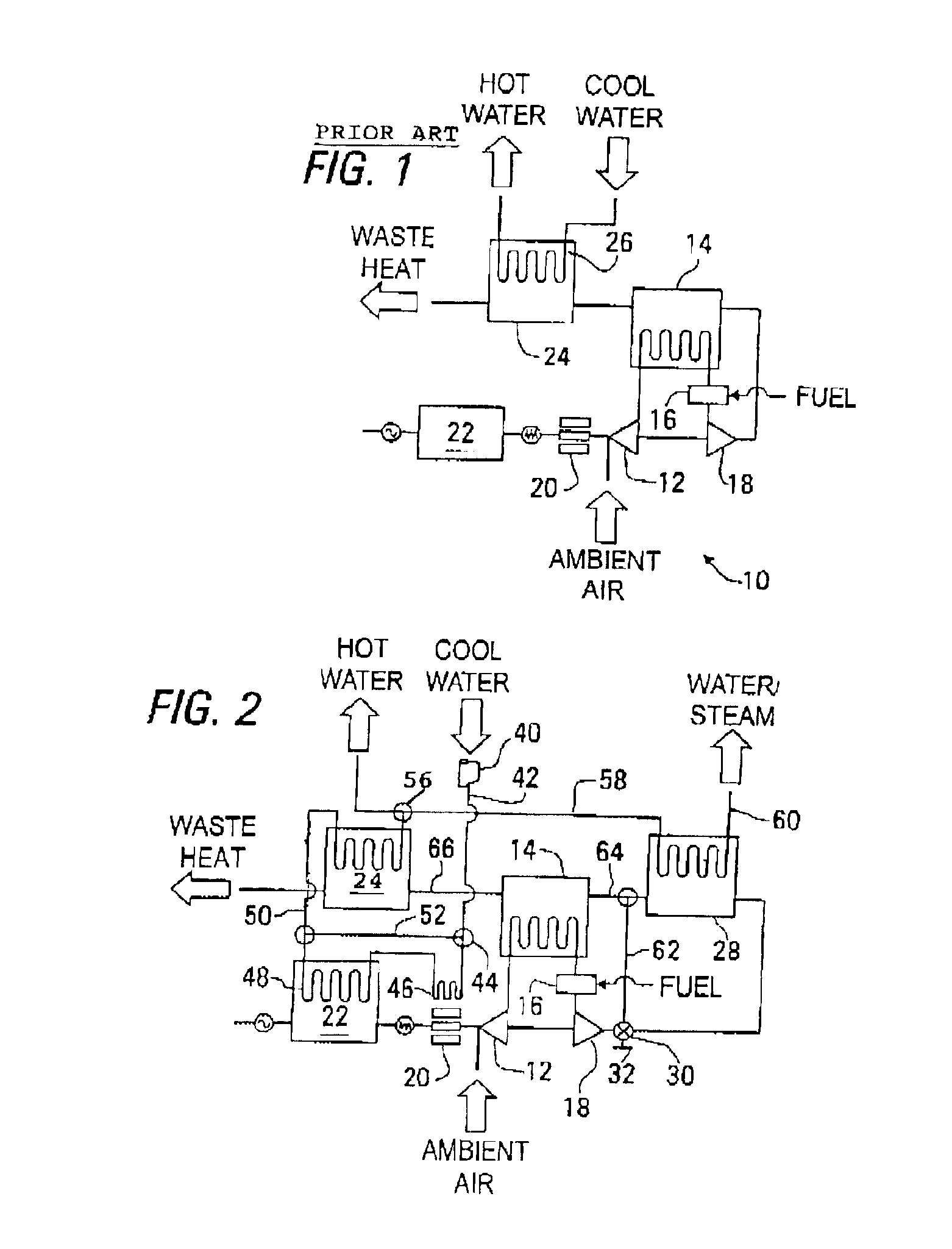
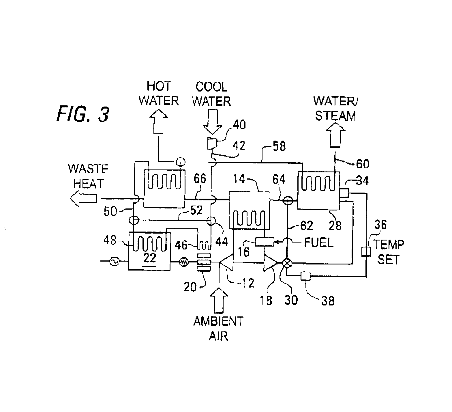
While this invention pertains to a microturbine system powering an electrical generator it is to be understood that the microturbine can be utilized for other types of systems and hence, is not limited to an electrical generating system. The microturbine engine has become popular in the last several years and essentially is a jet engine that includes a turbine, compressor, combustor and recuperator. The microturbine is a miniaturized gas turbine engine that in recent years have been almost totally utilized for powering electrical generators. In certain configurations, the turbine and compressor are attached back-to-back on one end of a shaft that is common to the shaft connecting the armature of the electrical generator. Fuel and relatively hot pressurized air discharging from the compressor and pre-heated by the recuperator are fed to an annular combustor where they are combined and combusted to further heat and accelerate the engine's working medium for powering the turbine. The e...


PUM


Abstract

The microturbine engine that is typically utilized to power an electrical generating system and/or boiler, chiller and the like includes a second boiler and a by-pass system for providing heated water at two different levels or where one of the boilers provides steam. The turbine exhaust is utilized as the heat transport medium and is directly connected to one of the boilers while the other is connected to the recuperator. The system can optionally provide cooling to the electrical and electronic components of the system by providing a water circuit for leading water into the electric and electronic components prior to feeding the boilers. The system is designed to assure that the delta heat difference between the medium being heated and the waste heat of the turbine is sufficient so that the heat exchange will be done efficiently.

Description

TECHNICAL FIELDThis invention relates to microturbines engines and more particularly to a system for generating hot water in a boiler and for selectively boosting the temperature of the medium for heat exchange relation by utilizing the turbine exhaust.BACKGROUND OF THE INVENTIONAs one skilled in this art appreciates the microturbine has in the last few years become extremely useful for generating electricity. Typically, the microturbine comprises a compressor, combustor, turbine and a recuperator which serves to pre-heat the compressor discharge air prior to being injected into the combustor. The work produced by the turbine serves to rotate the armature of the electrical generator and an invertor converts the electrical current and controls its frequency. Details of the microturbine can be obtained by referring to co-pending patent application Ser. No. 09 / 934,640 filed on Aug. 22, 2001 by William R. Ryan entitled RECUPERATOR FOR USE WITH TURBINE / TURBO-ALTERNATOR, published and U.S...

Claims


Application Information

Patent Timeline
IPC IPC(8): F01K23/10F01K27/00F01K27/02F02C6/18F24D18/00
CPCF01K23/10F02C6/18F01K27/02F24H2240/06F24D2101/10F24D2103/13F24D18/00
Inventor DEWIS, DAVID W.
Owner WELLS FARGO BANK NAT ASSOC
Why Eureka
Try Eureka