Liquid heating apparatus and liquid heating method

a technology of liquid heating apparatus and liquid heating method, which is applied in the direction of fluid heaters, liquid transferring devices, lighting and heating apparatus, etc., can solve the problems of consuming radicals without contributing to cleaning, autolyzing of cleaning fluid, etc., and achieve uniform flow through the flow channel , uniform heat of liquid, and substantially constant flow

Active Publication Date: 2011-10-27
KURITA WATER INDUSTRIES LTD
View PDF40 Cites 3 Cited by
  • Summary
  • Abstract
  • Description
  • Claims
  • Application Information

AI Technical Summary

Benefits of technology

[0032]Since a liquid heating apparatus according to the present invention includes: a flow channel member forming a flow channel allowing liquid to flow and having flow channel thickness of 10 mm or smaller, the flow channel member composed of material transmitting near-infrared rays; and a near-infrared heater placed over the outside of at least one of opposite flow channel surfaces of the flow channel and heating the liquid in the flow channel, it is possible to instantaneously and evenly heat the liquid.
[0033]From the point of view of instantaneous and even heating of liquid, it is more preferable that the flow channel thickness is 5 mm or smaller. Further, in order to secure sufficient liquid flow, the flow channel thickness is preferably 1 mm or bigger, more preferably 2 mm or bigger. Moreover, in order to allow fluid to evenly flow through the flow channel, it is preferable that the flow channel thickness be substantially constant.
[0034]Since near-infrared rays pass through quartz, a flow channel member and spacers composed of quartz do not prevent heat transfer, and it is possible to efficiently transfer heat.
[0035]Since it is difficult to delicately process quartz, it has been difficult to form a flow channel having a narrow flow channel area, that is, small volume. According to another present invention using spacers, however, a flow channel having an appropriately narrow flow channel area can be formed by simple work, i.e., inserting the spacers into a flow channel of a quartz tube commercially available.
[0036]According to the present invention, the shape of spacers is not particularly limited. Spacers may be rod-shaped or granular-shaped, for example. In case of rod-shaped or granular-shaped spacers, small clearance is formed between a flow channel and each spacer by making the diameter of spacers some smaller than flow channel thickness, and liquid thus rapidly flows.
[0037]According to another aspect of the present invention, since pressure loss is provided by forming a header at a liquid inlet portion and a small hole such as an orifice at between the header and a flow channel performing heating, it is possible to equalize the distribution of flow volume within a flow channel even in case of a narrow flow channel, that is, in such a case where plural spacers are inserted therein, for example. Note that the residence time of high-temperature liquid can be shortened by reducing the volume of a header at a liquid outlet portion.

Problems solved by technology

Radicals have only short lifetime, and therefore, if the temperature of cleaning fluid is raised earlier, peroxosulfuric acid in the cleaning fluid will autolyze too early and its radicals will be consumed without contributing to cleaning.

Method used


Image

  • Liquid heating apparatus and liquid heating method
  • Liquid heating apparatus and liquid heating method
  • Liquid heating apparatus and liquid heating method

Examples


first embodiment

[0049]A liquid heating apparatus according to an embodiment of the present invention will be described below.

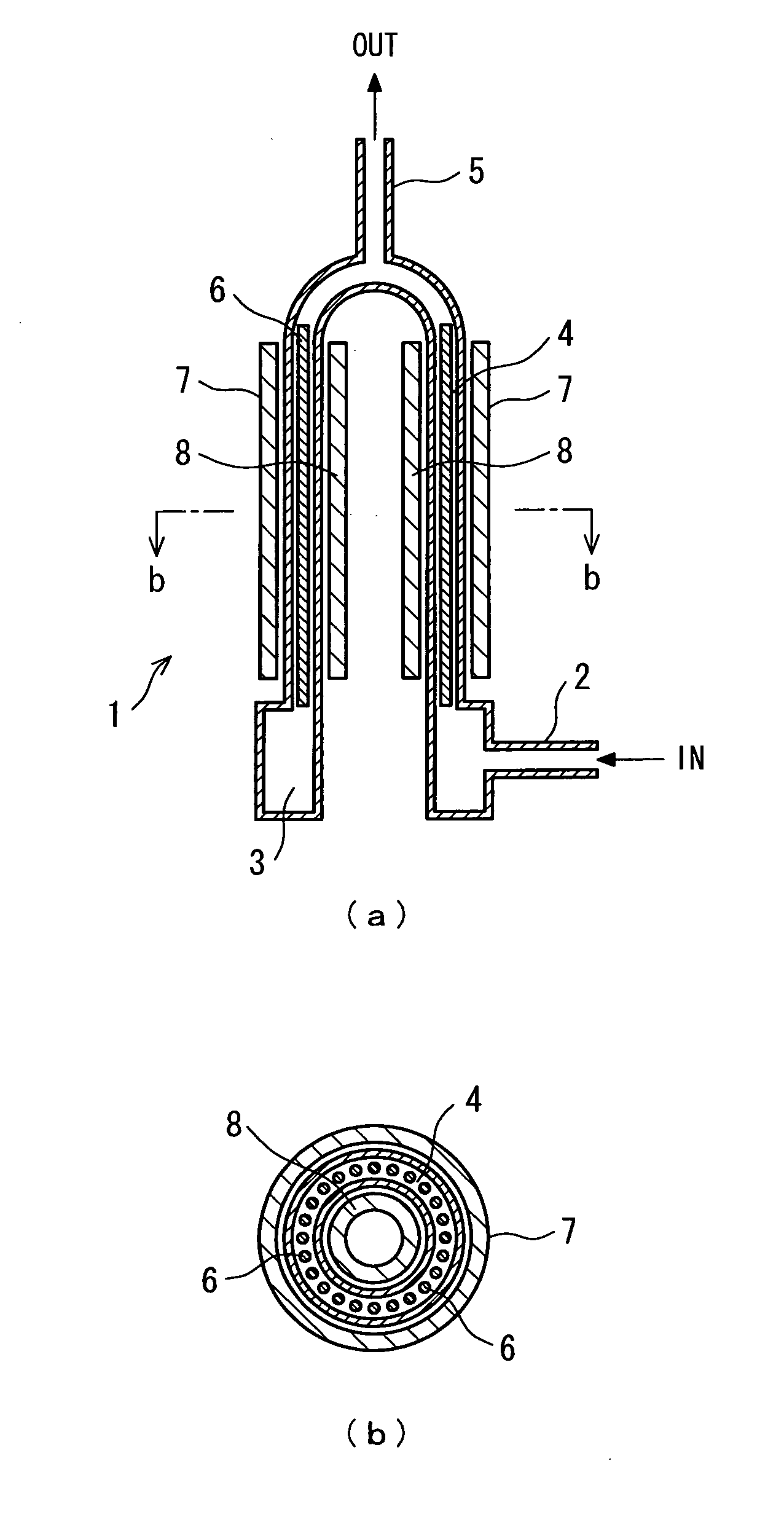
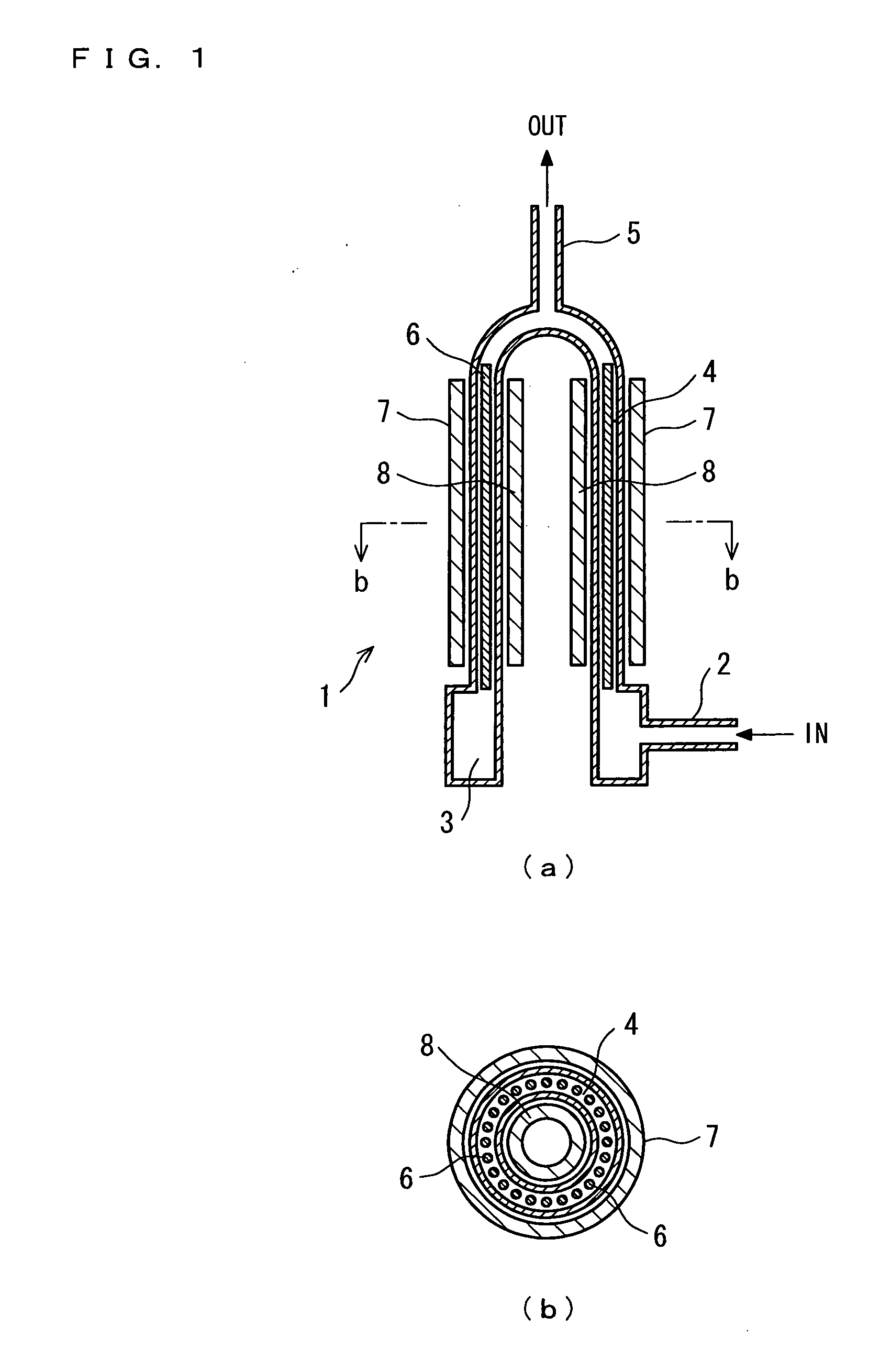
[0050]FIG. 1 is a schematic diagram of the liquid heating apparatus 1.

[0051]An annular flow channel 4 is formed with a double-tube structure where the diameters of two tubes are approximate as shown in the figure; that is, the annular flow channel 4 is provided between an inner tube and an outer tube, and its flow channel thickness is set at 10 mm or smaller. It is preferable that the annular flow channel 4 is vertically installed. In the installed condition, a tubular large-volume header 3 communicates with the lower side (liquid inflow side) of the annular flow channel 4. The header 3 is provided with a lower inflow port 2. Liquid to be heated flows into through the lower inflow port 2, and upward flow along the direction of the axis of the annular flow channel 4 is thereby generated in the annular flow channel 4 through the header 3. The upper side of the annular flow chan...

second embodiment

[0066]In the liquid heating apparatus 1 according to the first embodiment, the upper side of the annular flow channel 4 is gradually reduced a diameter and concentrated to the center. Instead of the annular flow channel 4 reduced at an end to collect solution, a flow channel may extend while keeping annular shape. Another embodiment of the liquid heating apparatus according to the present invention will be described below with reference to FIG. 5.

[0067]A liquid heating apparatus 20 according to this embodiment has an annular flow channel 21 including a double-wall quartz tube, and the flow channel thickness of the annular flow channel 21 is set at 10 mm or smaller. Tubular headers 22 and 23 formed by partially making a flow channel thickness wider are provided, respectively, continuously with both ends of the annular flow channel 21. The header 22 at one end is provided at a liquid inlet portion, and an inflow tube 24 along longitudinal direction of the annular flow channel 21 is co...

third embodiment

[0069]In the second embodiment, near-infrared heaters are placed on both the outer circumference side and the inner circumference side of the annular flow channel. In one embodiment of the present invention, however, near-infrared heaters may be placed over the outside of only one of opposite flow channel surfaces of a flow channel.

[0070]A liquid heating apparatus 30 shown in FIG. 6 has an annular flow channel 31 made of quartz, and having flow channel thickness of 10 mm or smaller. Tubular headers 32 and 33 formed by making flow channel thickness greater are, respectively, continuous with both ends of the annular flow channel 31. The header 32 at one end is provided at a liquid inlet portion, and an inflow tube 34 is connected to the header 32. The header 33 at the other end is provided at a liquid outlet portion, and an outflow tube 35 is connected to the header 33. Plural rod-shaped spacers 36 along longitudinal direction of the annular flow channel 31 are arranged in rows across...


PUM


Abstract

Provided is a liquid heating apparatus capable of heating fluid such as peroxosulfuric acid solution to high temperature in a short time. The heating apparatus includes: a flow channel member forming a flow channel 4 allowing liquid to flow and having flow channel thickness of 10 mm or smaller, the flow channel member composed of material transmitting near-infrared rays; and a near-infrared heaters 7, 8 placed over the outside of at least one of opposite flow channel surfaces of the flow channel and heating the liquid in the flow channel. The liquid flowing through the flow channel is instantaneously and evenly heated using near-infrared rays. It is preferable that spacers 6 be further provided within the flow channel 4 in order to limit the volume of the flow channel. Since not only the residence time in the heating apparatus can be shortened but the possible largest heat transfer area can be also maintained by decreasing the volume of the flow channel of the heating apparatus and by increasing the flow velocity in the heating apparatus, it is possible to increase the temperature of liquid to be heated to high temperature in a very short time even if the preset temperature of heat transfer surfaces is low.

Description

TECHNICAL FIELD[0001]The present invention relates to a liquid heating apparatus capable of highly efficiently heating liquid in a short time. The present invention particularly relates to a liquid heating apparatus that can be suitably used to rapidly heat cleaning fluid at a resist stripping step included in semiconductor manufacturing process and to a liquid heating method therefore.BACKGROUND ART[0002]As a method used at a resist stripping step in semiconductor fabrication, a sulfuric acid electrolytic method has been known wherein sulfuric acid solution is electrolyzed to form peroxosulfuric acid (peroxodisulfuric acid: molecular peroxosulfuric acid and ionic peroxosulfuric acid) and then cleaning is performed using the peroxosulfuric acid solution as cleaning fluid. Resist stripping efficiently proceeds at a resist stripping step, when the temperature of cleaning fluid is elevated (to about 120° C. to 190° C.). It can be considered that this is because when the temperature of ...

Claims


Application Information

Patent Timeline
Patent Type & Authority Applications(United States)
IPC IPC(8): F24H1/10
CPCF24H1/101H05B3/10F24H1/162F24H1/121F24H9/0015F24H2250/14F24H1/10
Inventor UCHIDA, MINORUMARUYAMA, TSUYOSHI
Owner KURITA WATER INDUSTRIES LTD
Why Eureka
Try Eureka