Pivoting arm for seeders

Inactive Publication Date: 2006-09-12
SEEDMASTER MFG
View PDF3 Cites 21 Cited by
  • Summary
  • Abstract
  • Description
  • Claims
  • Application Information

AI Technical Summary

Benefits of technology

[0016]Thus lateral forces at the pivot mechanism are resisted by the pivot plate and arm bearing against the wear pads and the pivot bracket, rather

Problems solved by technology

These high lateral forces cause substantial stress on the pivot mechanism attaching the arm to the frame.
The furrow opener is often a considerable distance from the pivot mechanism, such that considerable torque is applied, multiplying the lateral force exerted on the mechanism.
In addition to providing the required pivotal movement of the arm, the pin also exerts the forces required to resist the lateral forces exerted on th

Method used


Image

  • Pivoting arm for seeders
  • Pivoting arm for seeders
  • Pivoting arm for seeders

Examples


Embodiment Construction

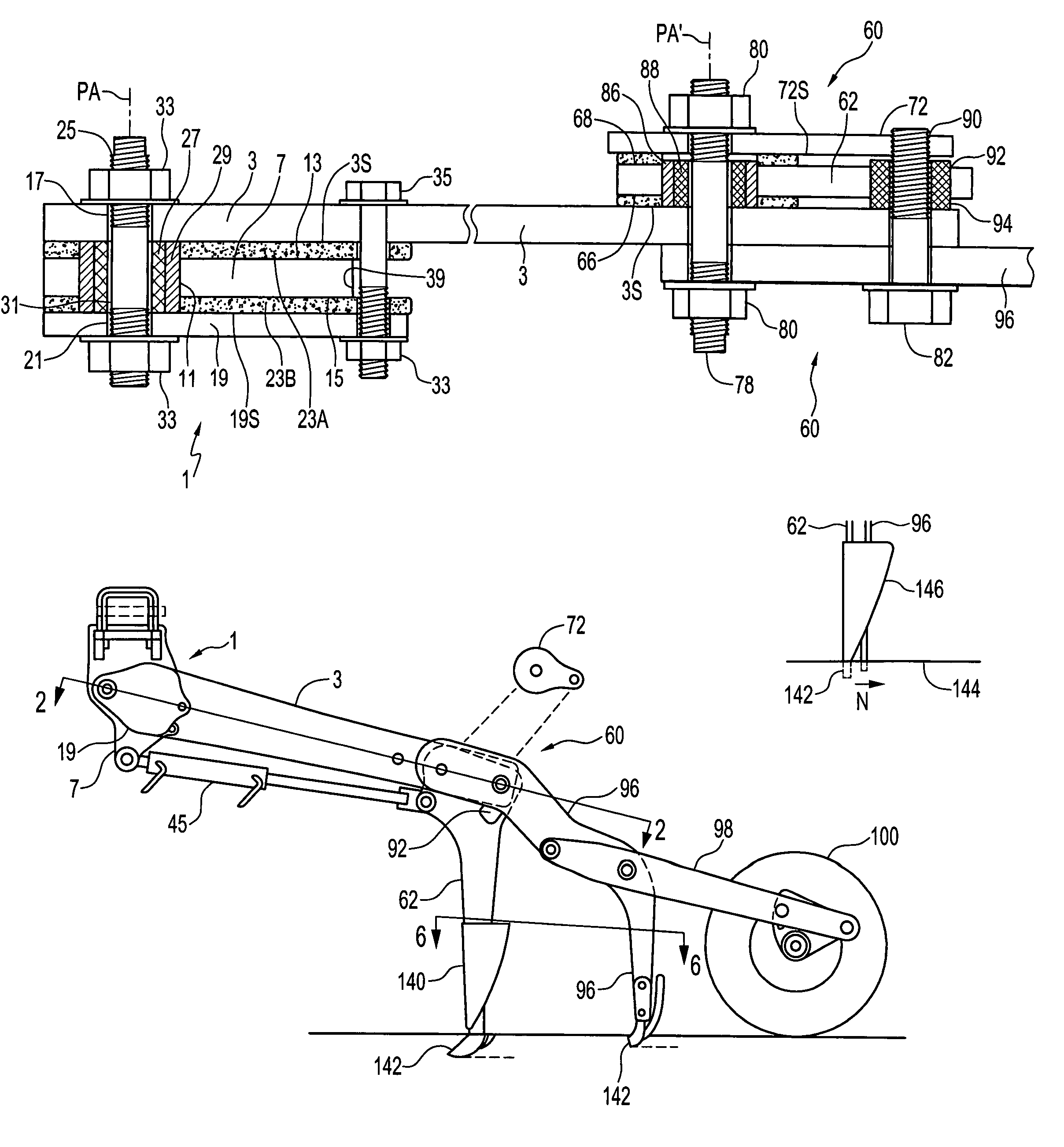
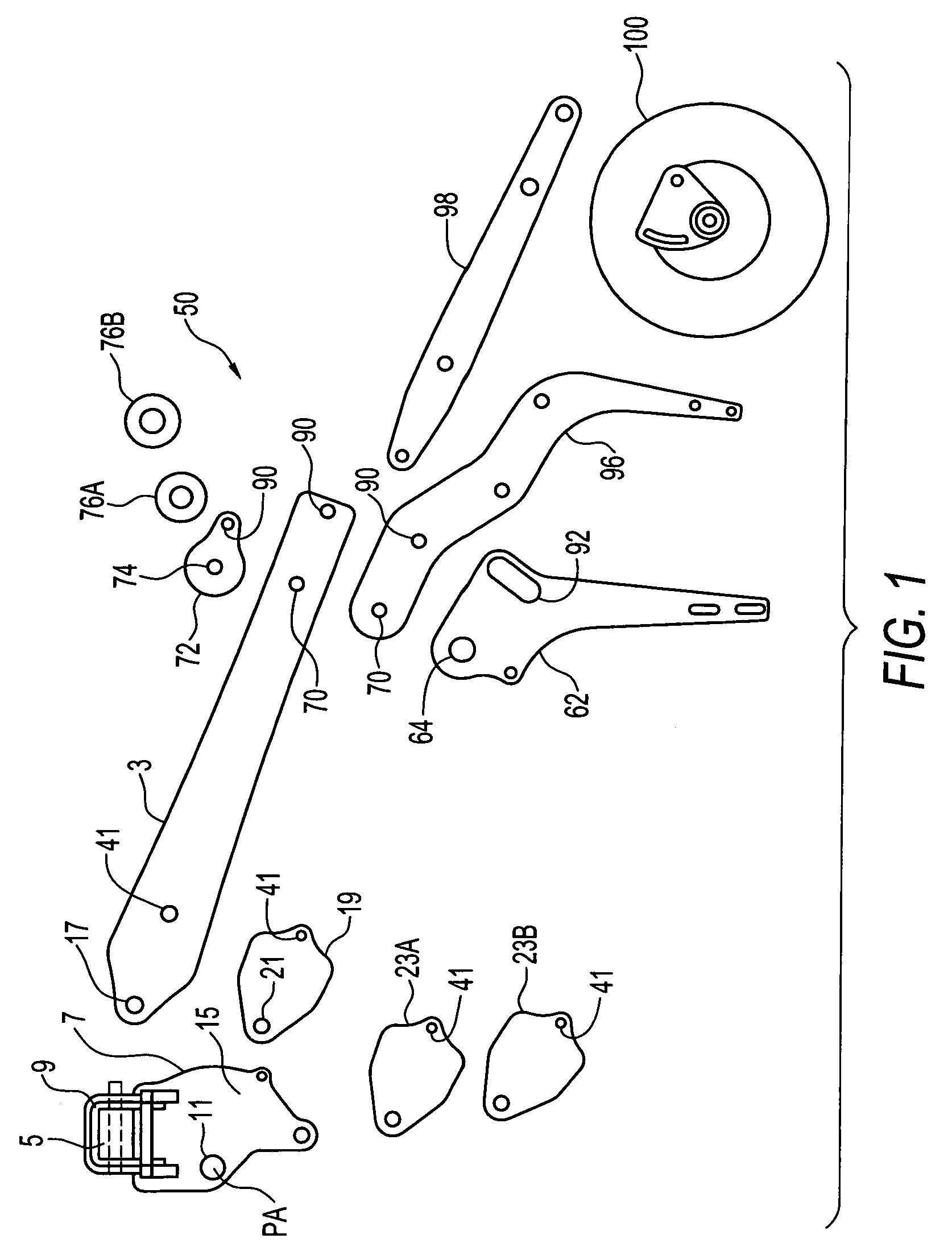
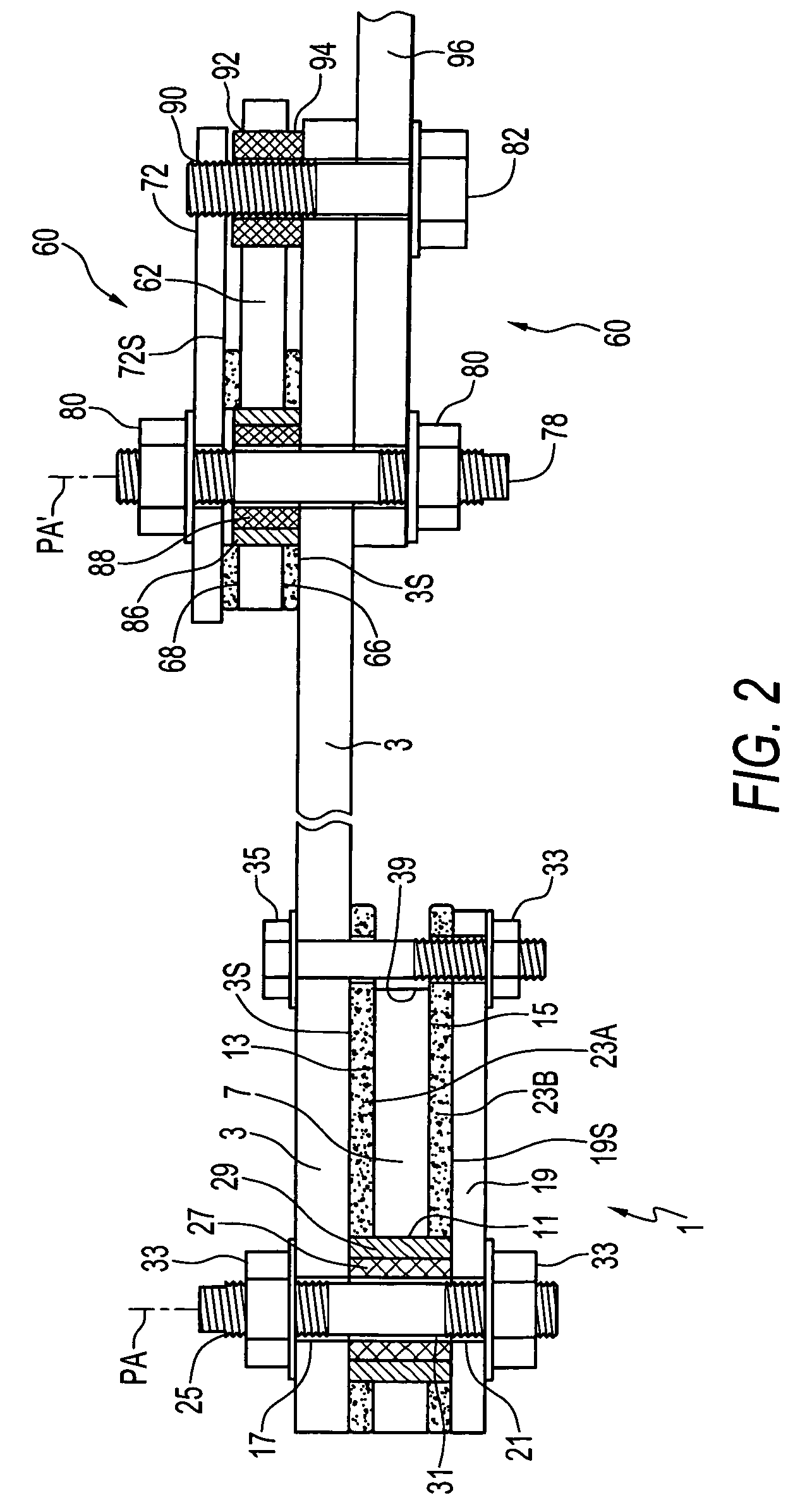
[0027]FIGS. 1 and 2 illustrate a pivot mechanism 1 of the invention for attaching an arm 3 to an implement 5 about a pivot axis PA. The illustrated embodiment is shown pivotally attaching a furrow opener apparatus 50 to an air seeder. FIG. 3 illustrates the furrow opener apparatus 50 in its assembled form.

[0028]The pivot mechanism 1 comprises a pivot bracket 7 attached to the implement 5 by U-bolts 9 as illustrated, or by welding or the like. The pivot bracket 7 defines a bracket pivot hole 11, and has first and second bracket surfaces 13, 15 oriented substantially perpendicular to the pivot axis PA.

[0029]The arm 3 defines an arm pivot hole 17 aligned with the bracket pivot hole 11 such that an inner surface 3S of the arm 3 is substantially parallel to the first bracket surface 13. A pivot plate 19 defines a plate pivot hole 21 aligned with the bracket pivot hole 11 such that an inner surface 19S of the pivot plate 19 is substantially parallel to the second bracket surface 15.

[0030]...


PUM


Abstract

A pivot mechanism for pivotally attaching two members about a pivot axis comprises a first member defining a first pivot hole, and having first and second bearing surfaces oriented perpendicular to the pivot axis. A second member defines a second pivot hole aligned with the first pivot hole, and a pivot plate defines a plate pivot hole aligned with the first and second pivot holes such that inner surfaces of the second member and pivot plate are parallel to the bearing surfaces. Wear pads are located between the inner and bearing surfaces. A pivot pin extends through the pivot holes. The pivot plate and second member are squeezed against the wear pads, and the second member and the pivot plate rotate together with respect to the first member. A residue deflector deflects residue clumps falling off a front seeder leg away from the path of a rear seeder leg.

Description

[0001]This invention is in the field of agricultural implements and like machines, and in particular pivoting members, such as the arms commonly used for a furrow opener, pivotally attached to a frame or the like.BACKGROUND[0002]Agricultural air seeders generally comprise a furrow opener arm pivotally attached to the frame. A furrow opener such as a disc, knife or hoe can be attached to a bottom end of the arm to engage the soil. The arm is maintained in a generally downward operating position by a bias element, and the mounting is such that the arm can move rearward and upward from the operating position, against the bias force, to clear obstacles or follow terrain.[0003]Alternatively, on some air seeders an arm extends rearward and the operating position is dictated by a wheel attached to the rear end of the arm. The arm moves up and down against a downward force exerted by a bias element, following changes in terrain as the wheel moves up and down relative to the frame. Typically...

Claims


Application Information

Patent Timeline
IPC IPC(8): A01B49/04A01C5/00A01B63/24A01C5/06
CPCA01C5/062A01B63/24
Inventor BEAUJOT, NORBERT
Owner SEEDMASTER MFG
Why Eureka
Try Eureka