Rigid air ducting for respirator hoods and helmets

a technology for respirator hoods and helmets, applied in the direction of hats, breathing masks, breathing protection, etc., can solve the problems of insufficient air flow, unstable shape and volume cabs, and reduced air flow

Inactive Publication Date: 2006-09-12
3M INNOVATIVE PROPERTIES CO
View PDF33 Cites 30 Cited by
  • Summary
  • Abstract
  • Description
  • Claims
  • Application Information

AI Technical Summary

Benefits of technology

[0018]The present invention seeks to provide an improved respirator, especially an improved respirator...

Problems solved by technology

A problem with known respirator hoods is that the air duct is regularly made of soft, flexible material similar to the hood.
As a result, the shape and volume cab be unstable, and local variations in the cross-section of the air duct can occur from day-to-day and from one hood to another.
Variations in duct cross-section can restrict the air flow the user and, in extreme cases, the duct may even close to shut-off the air supply.
A reduced air flow may be insufficient to provide the user with an acceptable volume of breathable air and to flush exhaled air containing a higher carbon dioxide content from the hood.
As a result, a build-up of carbon dioxide may occur, giving rise to potentially serious health and safety risks.
For example, the user may become dizzy, feel claustrophobic, and eventually collapse.
This can be a problem when the hoods are connected to a portable breathable air supply or a separate, remote air supply.
Variations in air duct cross-section can also increase the back pressure that, in turn, affects battery performance for the portable powered air supply.
In particular, the turbo unit must work harder to overcome the higher ba...

Method used


Image

  • Rigid air ducting for respirator hoods and helmets
  • Rigid air ducting for respirator hoods and helmets
  • Rigid air ducting for respirator hoods and helmets

Examples


second embodiment

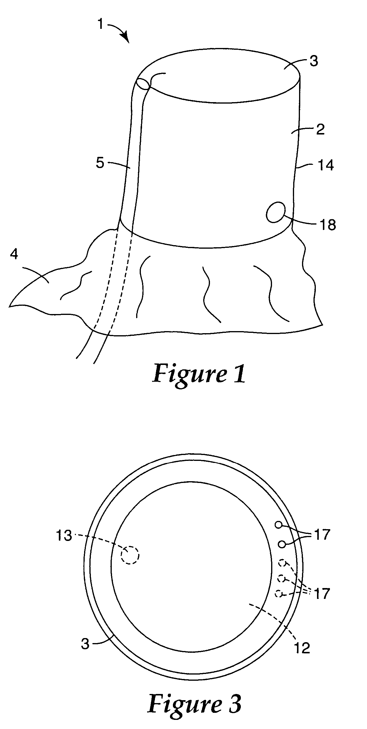
[0088]In FIG. 8, a respirator hood according to the invention is shown in which like reference numerals in the series 100 are used to indicate parts corresponding to FIGS. 1 to 3.

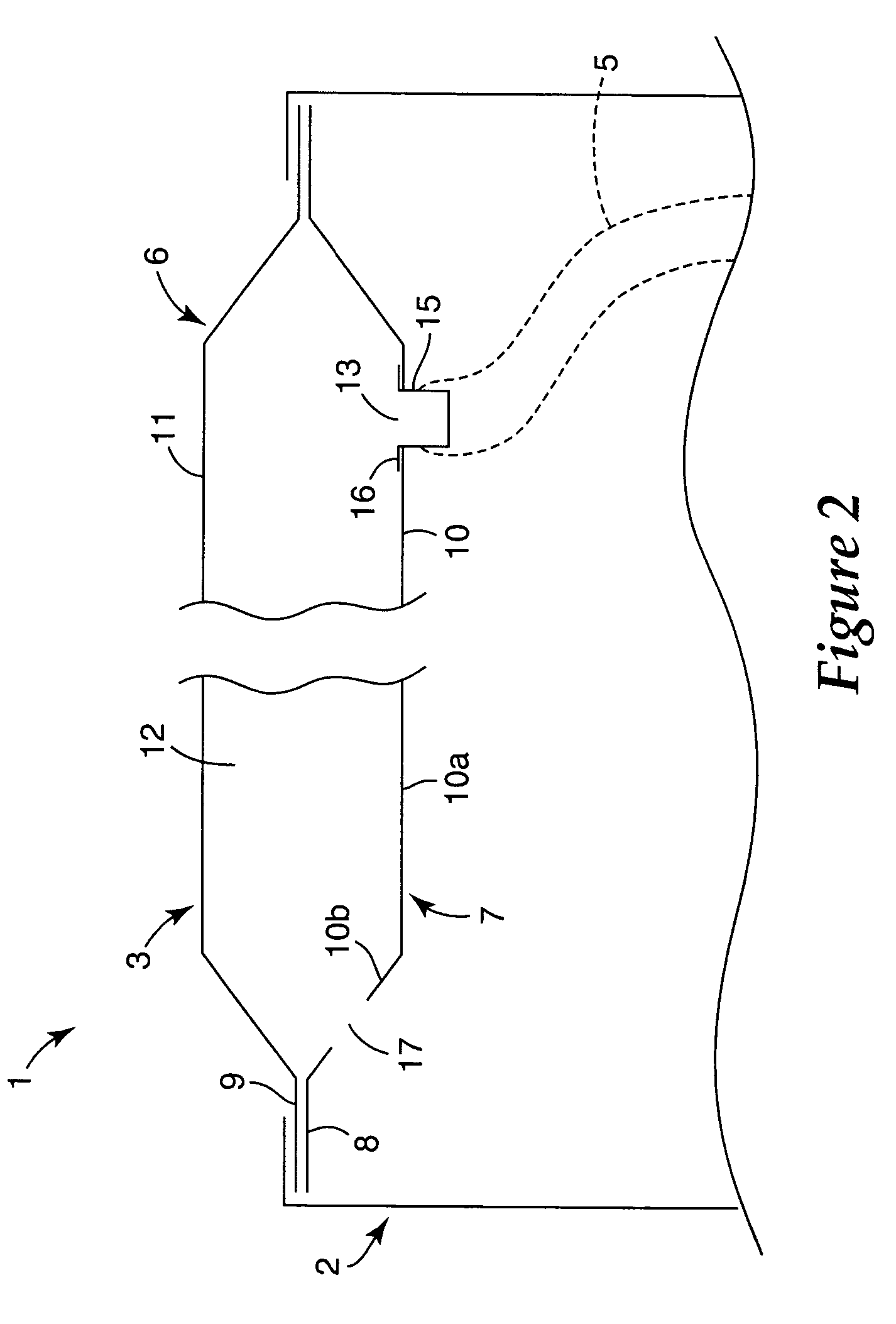
[0089]In this embodiment, the upper end of the side wall 102 is turned over and secured in fluid tight manner by welding or adhesive bonding to the edge flange 109 of the top wall 103 as previously described. The internal wall 107 is inserted into the hood 101 and is releasably secured in a substantially fluid tight manner to the underside of the top wall 103 around the perimeter of the hood 101 to form the air chamber 106. Any suitable means (not shown) may be used to secure the internal wall 107 such as by poppers with additional sealing where required.

first embodiment

[0090]In this way, the internal wall 107 can be removed and replaced if damaged or removed and re-used with another hood 101 if the hood 101 is designed to be disposable. In this arrangement, the hose 105 may be permanently attached to the internal wall 107 so as to be detachable with the internal wall 107 as a unit for cleaning, replacement or re-use. In other respects, the operation of the hood 101 is similar to the first embodiment and will be understood from the description thereof.

third embodiment

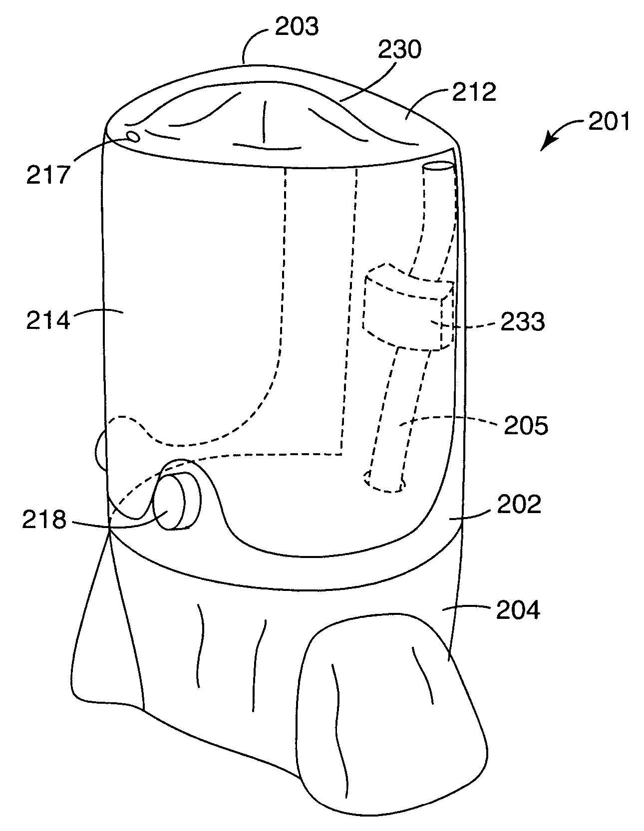
[0091]In FIGS. 9 to 12 of the drawings, there is shown a respirator hood according to the present invention in which like reference numerals in the series 200 are used to indicate parts corresponding to the previous embodiments.

[0092]In this embodiment, the shape of the top wall 203 and internal wall 207 is altered to reduce the overall height of the side wall 202 of the hood 201 and to allow styling of the shape of the hood 201 to enhance the appearance of the hood 201.

[0093]As shown 11, the hood 201 has an ovoid shape in plan view with the wider rounded end at the front of the hood 201 and the narrower rounded end at the rear of the hood 201.

[0094]The internal wall 207 has a dome-shaped central region 230 defining a recess 231 open to the underside in which the top of the head of the user can be received. The dome-shaped central region 230 is surrounded by a recessed channel 232 terminating in an outwardly directed edge flange 208.

[0095]The channel 232 is wider and shallower at th...


PUM


Abstract

A respirator hood 1 that has an air chamber 6 arranged above the head of a user for delivery of breathable air. The air chamber 6 has an air inlet 13 connected to an air supply hose 5 and an air outlet 17 The outlet 17 is arranged to direct air away from the eyes of the user. The air chamber 6 forms an air duct 12 that substantially covers the top of the hood 1 above the user's head. The duct 12 is collapse-resistant so that the duct shape is maintained in use and air flow through the duct 12 is substantially unrestricted. As a result, a substantially uniform air flow can be achieved in use, which air flow pattern is repeatable from day to day and from hood to hood.

Description

[0001]This application claims priority from Great Britain Application No. 0307198.2 filed Mar. 28, 2003.[0002]This invention pertains to respirator hoods and helmets that are worn on a user's head to provide breathable air to the hood / helmet interior.BACKGROUND[0003]Respirator hoods and helmets are well known and have many uses. For example, the hoods may be used to allow the user to breathe safely in a contaminated atmosphere, such as a smoke filled atmosphere, in a fire or a dust laden atmosphere, in a mine or a toxic atmosphere, or in a laboratory.[0004]Respirator hoods and helmets also may be worn where it is desired to prevent the user from contaminating the surrounding atmosphere, such as when working in a clean room used to manufacture silicon chips.[0005]Respirator helmets have a hard shell that provides head protection against impacts when working in a dangerous environment where the user is at risk of being struck by falling debris such as in a mine or on a building site.[...

Claims


Application Information

Patent Timeline
IPC IPC(8): A62B17/04A42C5/04
CPCA62B17/04
Inventor LEE, PETER D.HENDERSON, CHRISTOPHER P.
Owner 3M INNOVATIVE PROPERTIES CO
Why Eureka
Try Eureka