
Static two stage air classifier

a technology of air classifier and particle size, which is applied in the direction of gas current separation, solid separation, agriculture tools and machines, etc., can solve the problems of difficult control of horizontal air tunnel classifiers, invariably having moving parts or mechanisms which are prone to failure or suspect failure, and all such classifying devices have the potential for failur

Inactive Publication Date: 2006-09-12
COVIA HLDG CORP
View PDF45 Cites 33 Cited by
  • Summary
  • Abstract
  • Description
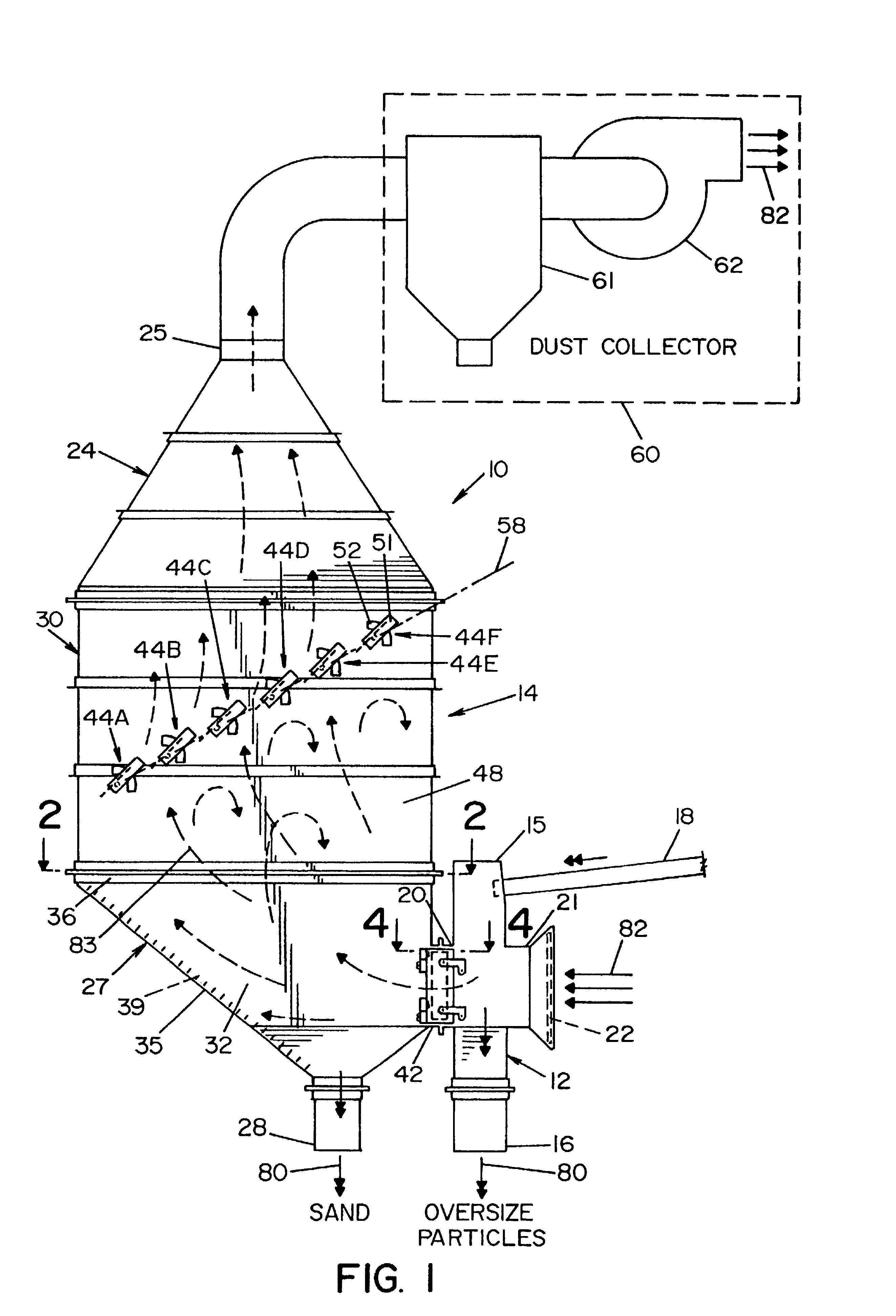
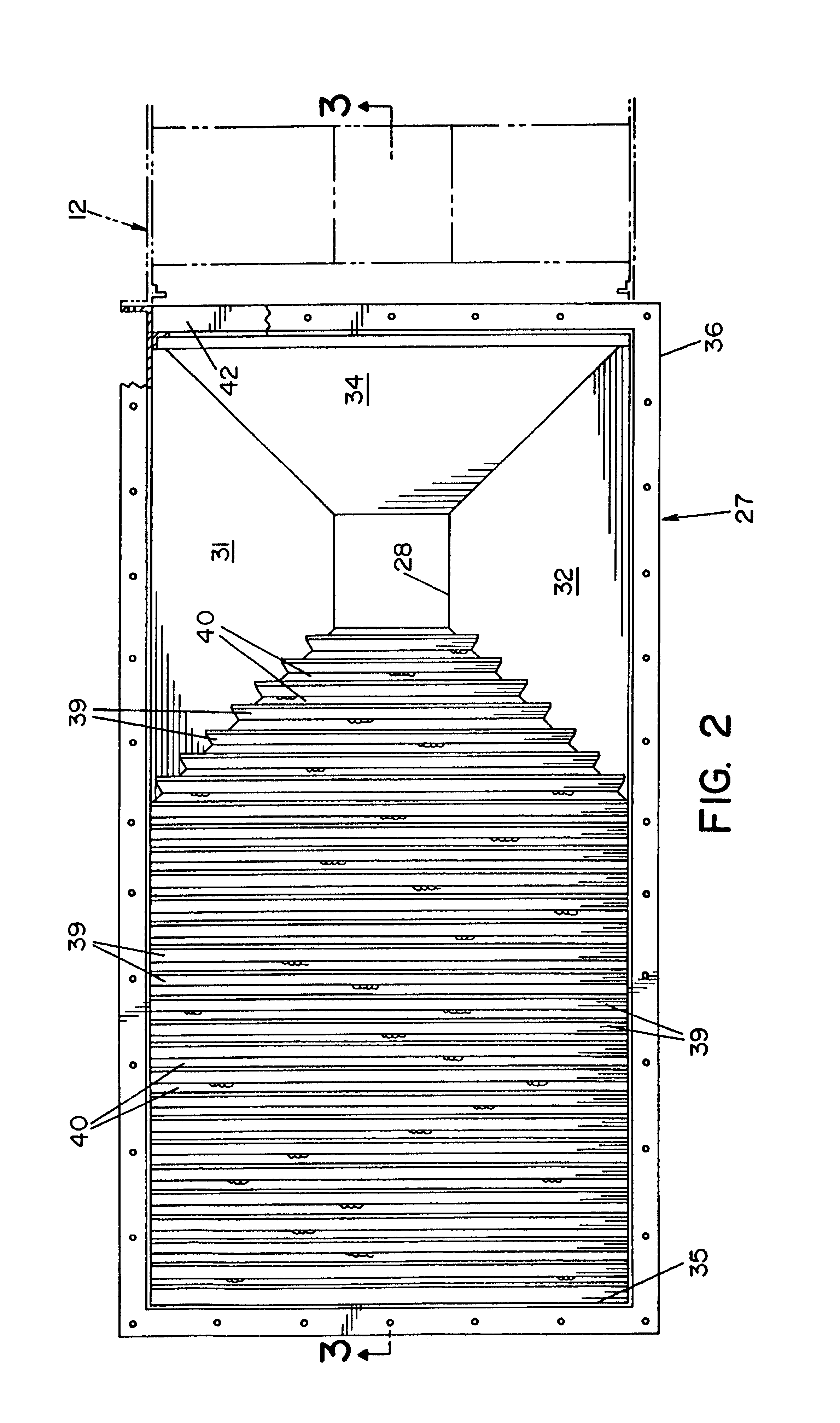
  • Claims
  • Application Information

AI Technical Summary

Benefits of technology

[0008]It is thus a principle object of the invention to provide a static air classifier (without classifying screens or moving parts) which is stable and consistent in operation.
[0009]This object along with other features of the invention is achieved in a device for separating and classifying particles of a homogeneous granular mixture which includes a generally vertically extending, open ended feed duct having a feed inlet at its top, an oversized discharge outlet at its bottom, a side exit opening in-between the duct's ends and a side air inlet opening generally aligned or in registry with the side exit opening on the opposite side of the duct. A feeder such as a vibratory feeder is provided for depositing a particle stream of the granular mixture into the duct at its feed inlet so that the granular mixture falls by gravity to the oversized discharge outlet. A separator box is provided adjacent the feed duct and has a top section with a dust collector outlet, a bottom section with a classifier outlet and an intermediate section therebetween with the bottom section of the separator box having a box inlet connected to the side exit opening of the feed duct. A classifying louver plate having a plurality of upwardly extending fins which define vertically inclined classifying channels between adjacent fins horizontally extends from the side exit opening of the feed duct to the separator box inlet. A fan adjacent the duct collector outlet is provided for pulling air from the duct air inlet opening through the classifying passages whereat particles beyond a preset size impinge the fins and fall back by gravity into the granular mixture in a first separating stage while particles less than the preset size remain entrained within the air flow and enter the separator box where the particles fall by gravity into the classifier outlet in a second collecting stage. By sizing the separator box and classifying plate flow areas, separation and collection of separated particles occurs in a stable manner by drawing air through the classifier and the rate at which the air is drawn can be variably set for collecting particles within desired size ranges.
[0010]In accordance with another aspect of the invention, the intermediate box section longitudinally extends in a generally vertical direction and includes a plurality of spaced baffle plates transversely extending across the intermediate box section. Each baffle plate is rotatable about a center which is positioned to lie in a vertically inclined plane. The baffle plates act as transversely speed impingement devices to insure that the air flow is thoroughly distributed across the intermediate box section and control air flow or velocity in the separator box to allow the separated particles to drop out of the air stream in the separator box and fall by gravity into the classifier outlet. More particularly, by adjusting the baffles to set positions, the content or quantity of fines (inherently present in the granular mixture) collected in the classifying outlet along with the separated particles can be controlled.

Problems solved by technology

All such classifying devices have the potential for failure if the screens are blocked.
Further, such classifying devices invariably have moving parts or mechanisms which are prone to or suspect of failure in the harsh environment of a granular mixture that inevitably produces or includes dust particles and fines.
However, such horizontal air tunnel classifiers are difficult to control.
“Pushed” air streams at low, laminar flow velocities are not stable and when the low velocities have to be slightly varied to allow particles within a set discriminatory size range to drop out of the air streams at set distances, controllability issues are present.

Method used


Image

  • Static two stage air classifier
  • Static two stage air classifier
  • Static two stage air classifier

Examples


Embodiment Construction

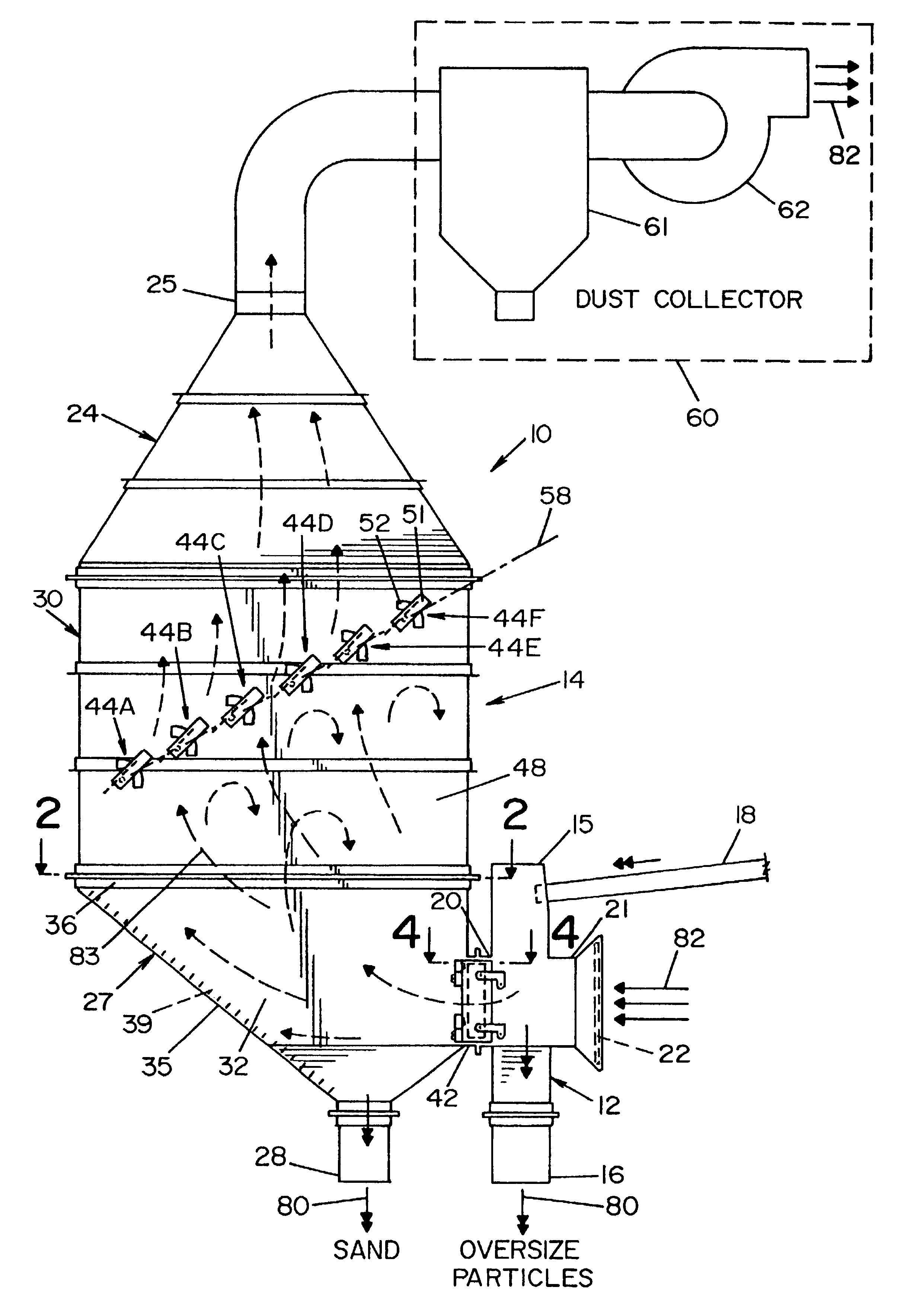
[0035]Referring now to the drawings wherein the showings are for the purpose of illustrating a preferred embodiment of the invention only and not for the purpose of limiting the same, there is shown in FIG. 1 an air classifier 10 of the invention.

[0036]In the preferred embodiment, air classifier 10 separates by size or “classifies” a granular mixture substantially comprising silica sand particles. For consistency in terminology only and when used in the specifications hereof to define the invention, “granular mixture” will refer to a substance comprising a plurality of discrete “particles” having various sizes and shapes even though technically there may be no difference between a “granule” and a “particle”. The granular mixture is homogeneous in the sense that all the particles are substantially of the same material (technically, the same density) albeit different size. At noted above, granular mixtures comprising particles of the same material other than silicon sand can be separa...


PUM


Abstract

A two-stage static air classifier has a feed duct through which particles of a granular mixture fall. A classifying louver plate having fins forming upwardly inclined classifying channels is fitted into a side opening in the feed duct. Particles of a set size are drawn by air suction through the classifying channels in the first stage. A separator box having an inlet connected to the outlet of the classifying channels collects the separated particles in a second stage as the entrained particles fall by gravity to the bottom of the separator box while the air streams drawing the particles through the classifying channels pass out the top end of the box. Adjustable baffle plates transversely extending through the box permit control of the quantity of fines collected with the particles at the separator box bottom. Size of the collected particles is determined by the speed of a fan at the top outlet of the separator box.

Description

[0001]This application is a continuation of Ser. No. 09 / 746,446, filed Dec. 20, 2000 now abandoned.[0002]This invention relates generally to method and apparatus for classifying granular products by size and more particularly to systems which classifying particles by means of air flow.[0003]This invention is particularly applicable to and will be described with specific reference to an air classifier system for sand, particularly silica sand used in industrial processes or in golf course sand traps. However, the invention has broader application and may be used in any system in which particles of a granular, homogenous substance must be classified or separated by size such as, for example, grain, pulverized coal, seeds, etc.BACKGROUND[0004]As a general definition, separating deices can be broadly divided into sorting devices which separate granular mixtures that contain different materials of different densities and classifying devices which separate particles of a homogeneous granu...

Claims


Application Information

Patent Timeline
IPC IPC(8): B07B9/00
CPCB07B7/04
Inventor STEPHENS, DAVID L.VERRET, GERALD G.LALANCETTE, RICHARD U.
Owner COVIA HLDG CORP
Learn More