Method and device for separating out contaminants from a pneumatic fibre stream

A separation and fiber technology, applied in the direction of separating solids from solids with airflow, solid separation, chemical instruments and methods, etc.

Inactive Publication Date: 2013-09-18
DIEFFENBACHER GMBH & CO KG
View PDF9 Cites 6 Cited by
  • Summary
  • Abstract
  • Description
  • Claims
  • Application Information

AI Technical Summary

Problems solved by technology

Fiber flow is guided along the bend

Method used


Image

  • Method and device for separating out contaminants from a pneumatic fibre stream

Examples


Embodiment Construction

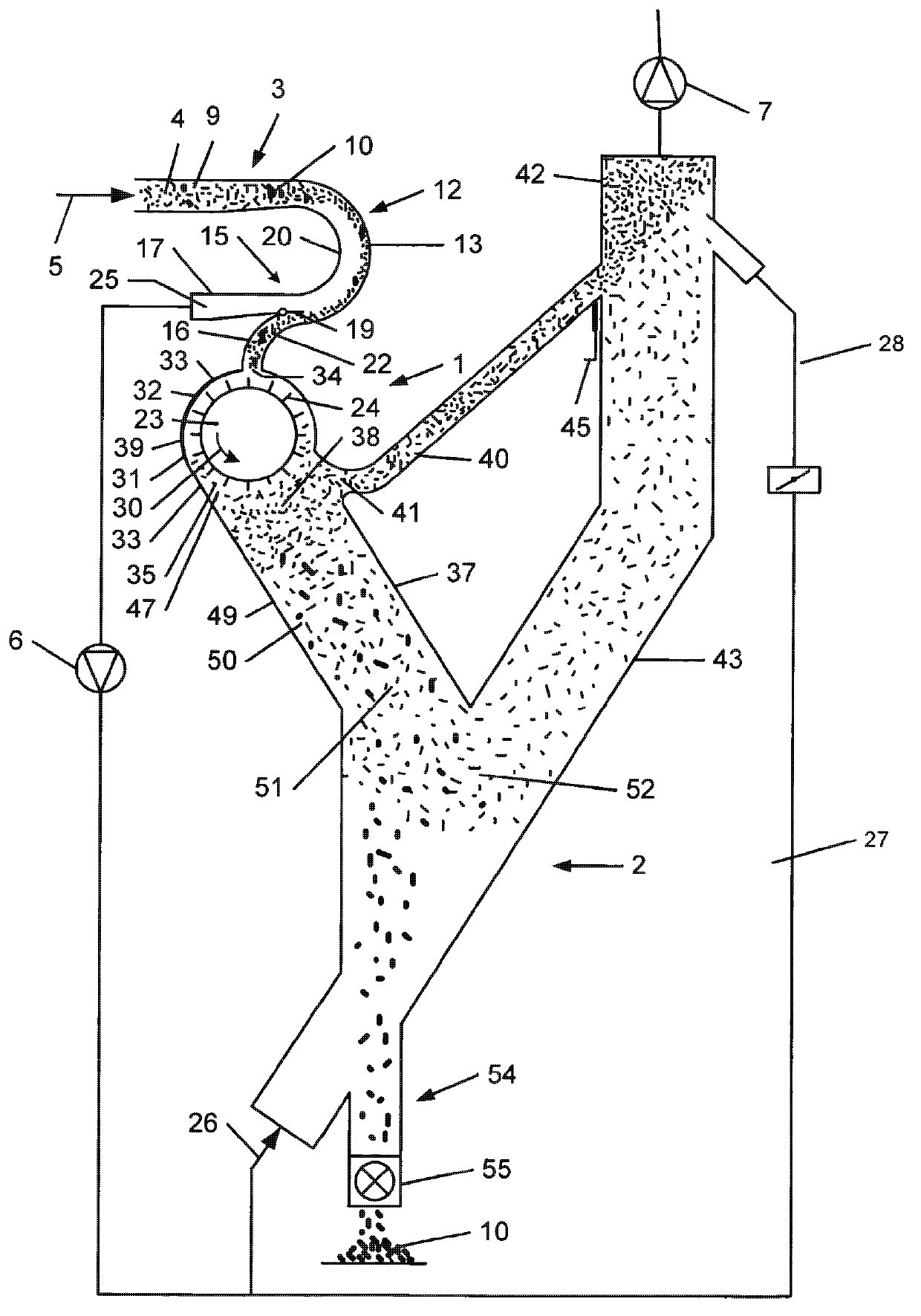
[0033] according to figure 1 is a device for separating pollutants in the form of coarse material 10 from a fiber gas stream used for the production of fibreboard. The plant consists of a pretreatment unit 1 and an air separator unit 2 . The device comprises a transport line section which guides the fiber gas flow 4 in the direction of the arrow 5 . Two fans 6 and 7 are connected to the transport line and create a negative pressure inside said transport line.

[0034] The fiber stream 4 is sucked by a device (not shown), which may be a dry fiber gluing device. Contaminants are also present in the form of relatively heavy particles between the fibers 9 representing normal material, these particles will hereinafter be referred to as coarse material 10 . The transport line section 3 is depicted as a bend 12 . This bend 12 is arranged in such a way that under the action of the centrifugal force acting on the bend 12, the fiber stream 4 will be placed on the outer area or outer...


PUM


Abstract

The invention relates to a method and a device for separating out contaminants in the form of coarse material (10) from a pneumatic fibre stream (4) intended for producing fibre boards, wherein the fibre stream is divided into a separating air stream (25), which merely contains air and normal material (9) consisting of fibres, and a main fibre stream (22), containing the coarse material (10) and normal material (9), by using centrifugal force, in that the fibre stream (4) undergoes a curvature (12), wherein the main fibre stream is conducted in an outer region (13) of the curvature and the separating air stream is sucked away in an inner region (20) of the curvature, wherein the main fibre stream is fed to a separating roller (23), which has a multiplicity of pins (24); on its surface and rotates in such a way that the impinging coarse material and normal material is deflected and conducted along a shaft portion (33) and the normal material is accelerated to approaching the circumferential speed of the roller in such a way that some of the normal material leaves the effective range of the roller with a horizontal movement component, wherein some of the normal material is sucked away through a suction removal line (40) and some of the normal material and the coarse material enter a drop shaft (37) and from the latter enter an air classifier unit (2), wherein at least some of the separating air stream is fed to the air classifier unit in such a way that it acts on the normal material and coarse material arriving from the drop shaft (37) and deflects the normal material into a normal-material suction removal shaft (43), while the coarse material enters a coarse material discharge (54). The method and the device can be integrated in an existing transporting line.

Description

technical field [0001] The present invention relates to a method and a device for separating contaminants in the form of coarse material from a fiber gas stream used for the production of fibreboard. The fiber flow may, for example, come from dry gluing, which involves an air flow generated by a negative pressure. The fibers are preferably made of lignocellulose and / or cellulose containing material. Fiberboard refers to light medium density fiberboard (MDF) and high density fiberboard (HDF). Background technique [0002] In known separation methods as disclosed in DE19718158A1, WO92 / 05882 and WO01 / 89783, the separator is integrated in the fiber-free air stream. Fibrous material is supplied to the separator via an external mechanical transport element. The disadvantage is that, due to the process, the fibrous material is always deployed in the air flow before separation, for example in a pneumatically conveyed dryer, the fibrous material needs to be conveyed to a mechanica...

Claims


Application Information

Patent Timeline
Patent Type & Authority Applications(China)
IPC IPC(8): B07B9/02B07B13/00B07B7/01B07B7/08B07B7/086B07B11/06
CPCB07B7/08B07B7/01B07B7/086B07B9/02B07B11/06B07B13/003B27N3/14
Inventor F·施奈德
Owner DIEFFENBACHER GMBH & CO KG
Why Eureka
Try Eureka