AI technical title is built by Patsnap AI team. It summarizes the technical point description of the patent document.
a technology of cooling turbine blades and turbine blades, which is applied in the direction of liquid fuel engines, vessel construction, marine propulsion, etc., can solve the problems of inadequate cooling in the leading edge region of turbine blades, and achieve the effect of improving the cooling of the leading edg
Active Publication Date: 2006-09-12
SIEMENS ENERGY GLOBAL GMBH & CO KG
View PDF15 Cites 65 Cited by
Summary
Abstract
Description
Claims
Application Information
AI Technical Summary
This helps you quickly interpret patents by identifying the three key elements:
Problems solved by technology
Method used
Benefits of technology
Benefits of technology
[0009]It is therefore the object of the invention to show a turbine blade in which the cooling of the leading edge is improved.
Problems solved by technology
However, the effectiveness of the cooling in the region of the leading edge of a turbine blade is inadequate.
Method used
Image
Click on the blue label to locate the original text in one second.
Reading with bidirectional positioning of images and text.
Examples
Embodiment Construction
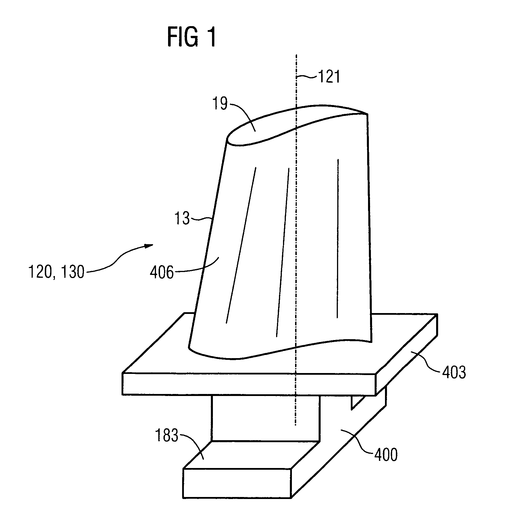
[0016]FIG. 1, in a perspective view, shows a blade 120, 130 (FIG. 3) which extends along a longitudinal axis 121 (radial direction).
[0017]The blade 120, 130 has, following one another along the longitudinal axis 121, a fastening region 400, an adjoining blade platform 403, a blade airfoil region 406 and a blade tip 19.
[0018]The blade airfoil region 406 is subjected to the flow of a medium at a leading edge 13.
[0019]Formed in the fastening region 400 is a blade root 183 which serves to fasten the moving blades 120, 130 to the shaft 103 (FIG. 3). The blade root 183 is of hammerhead configuration. Other configurations, for example as a fir-tree or dovetail root, are possible. In the case of conventional blades 120, 130, solid metallic materials are used in all the regions 400, 403, 406 of the moving blade 120, 130.
[0020]In this case, the moving blade 120, 130 may be produced by a casting process, by a forging process, by a milling process or by combinations thereof.
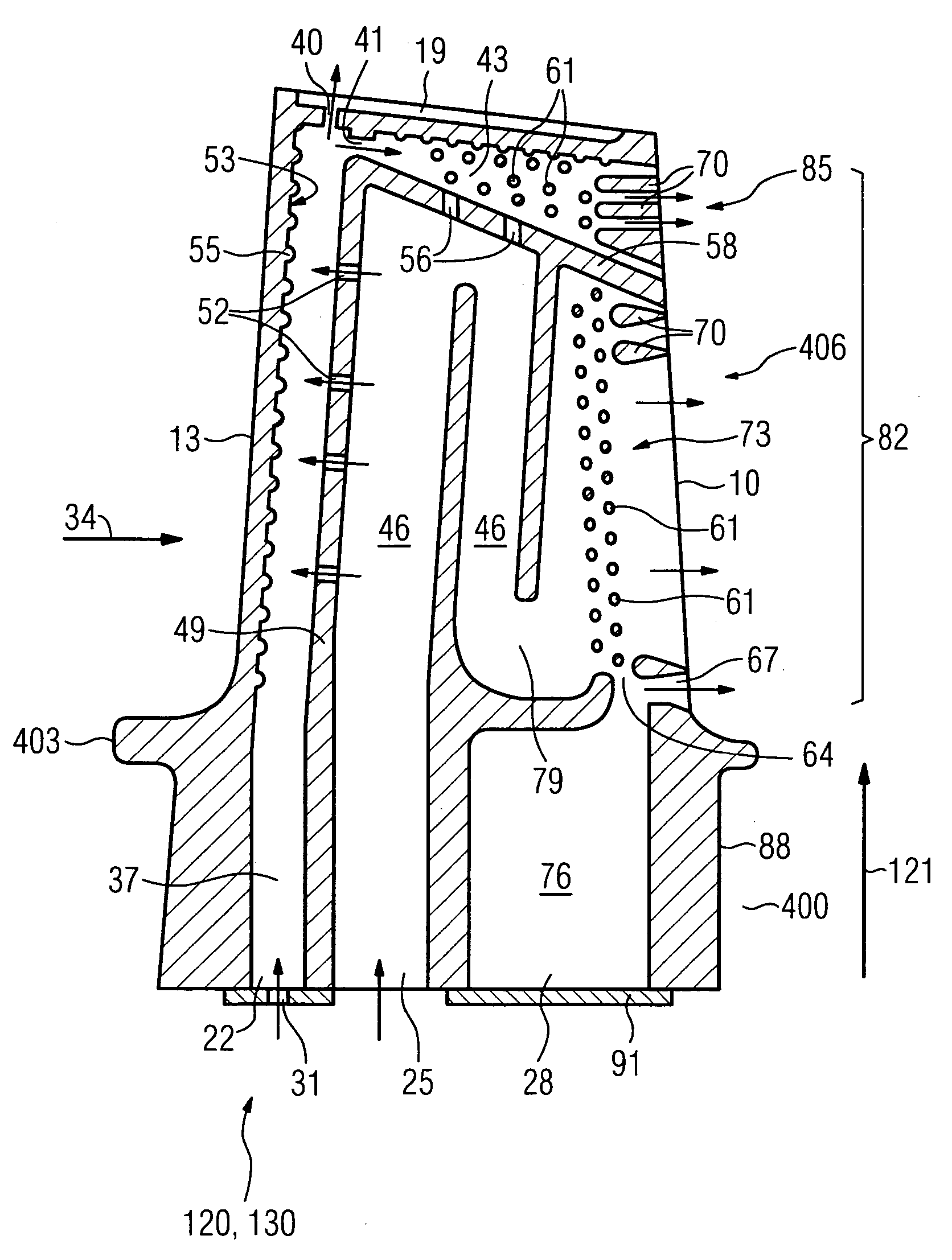
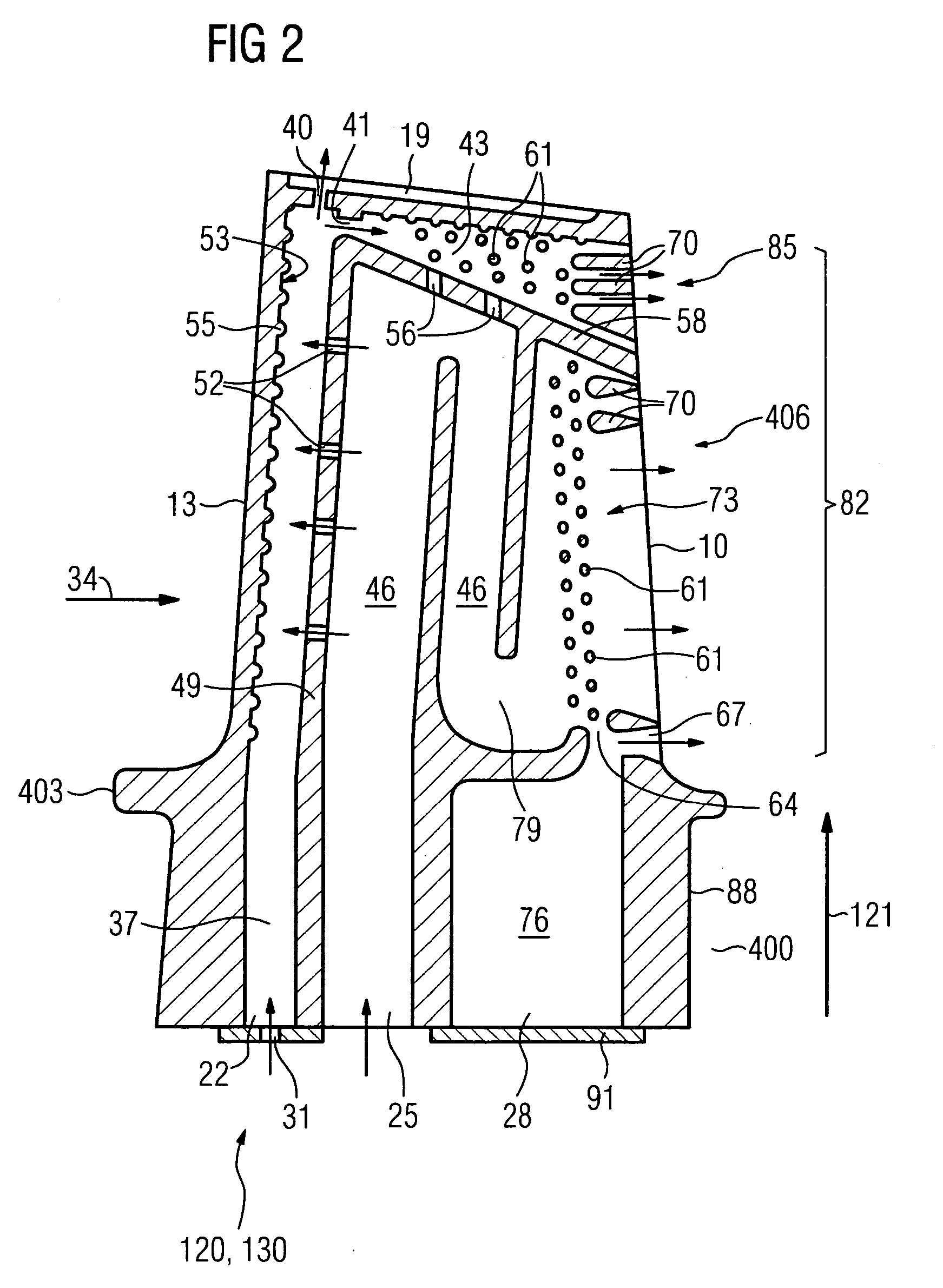
[0021]FIG. 2 shows s...
PUM
Abstract
The invention relates to a turbine blade which has a nose cavity in the region of a leading edge, it being possible for the leading edge to be cooled by impingement cooling, which has an inner cavity at least partly of meander-shaped design, and which has a crown pocket as cavity in the region of the blade tip, which crown pocket is connected to the nose cavity, so that the cooling of the turbine blade is improved.
Description
CROSS REFERENCE TO RELATED APPLICATION[0001]This application claims priority of the European application No. 03023643.4 EP filed Oct. 17, 2003 under the European Patent Convention and German application No. 10334899.9 DE filed Jul. 29, 2003, both of which are incorporated by reference herein in their entirety.FIELD OF THE INVENTION[0002]The invention relates to a coolable turbine blade as claimed in claim 1.BACKGROUND OF THE INVENTION[0003]Internally cooled turbine blades which have a meander-shaped inner region (EP 1 022 434 A2) and impingement cooling are known.[0004]The impingement cooling in the interior of turbine blades is likewise known.[0005]DE 32 34 906 A1, U.S. Pat. Nos. 5,857,837, 5,873,695, 5,902,093, 5,462,405, 6,139,269 show a turbine blade whose leading edge is cooled by impingement cooling.[0006]DE 199 63 716 A1, U.S. Pat. Nos. 4,474,532, 4,753,575 and 4,767,268 show a turbine blade which has a cavity in the region of its blade tip.[0007]U.S. Pat. No. 6,431,832 shows...
Claims
Application Information
Patent Timeline
Application Date:The date an application was filed.
Publication Date:The date a patent or application was officially published.
First Publication Date:The earliest publication date of a patent with the same application number.
Issue Date:Publication date of the patent grant document.
PCT Entry Date:The Entry date of PCT National Phase.
Estimated Expiry Date:The statutory expiry date of a patent right according to the Patent Law, and it is the longest term of protection that the patent right can achieve without the termination of the patent right due to other reasons(Term extension factor has been taken into account ).
Invalid Date:Actual expiry date is based on effective date or publication date of legal transaction data of invalid patent.

