
Electronic device with sheath structure

a technology of electronic devices and sheaths, which is applied in the direction of coupling device connections, instruments, computing, etc., can solve the problems of reducing the lifetime affecting the performance of the usb storage device, and no longer suitable conventional data storage devices, so as to prevent the connection portion from being contaminated or damaged

Inactive Publication Date: 2006-09-12
INVENTEC CORP
View PDF4 Cites 46 Cited by
  • Summary
  • Abstract
  • Description
  • Claims
  • Application Information

AI Technical Summary

Benefits of technology

[0006]In light of the drawback of the prior art, an objective of the present invention is to provide an electronic device with a sheath structure, for protecting a connection portion of the electronic device by a sheath, without having to use a detachable protective cover that is easily lost.
[0007]Another objective of the present invention is to provide an electronic device with a sheath structure, allowing a user to operate easily with one hand to make a connection portion of the electronic device covered by a sheath or exposed from the sheath.
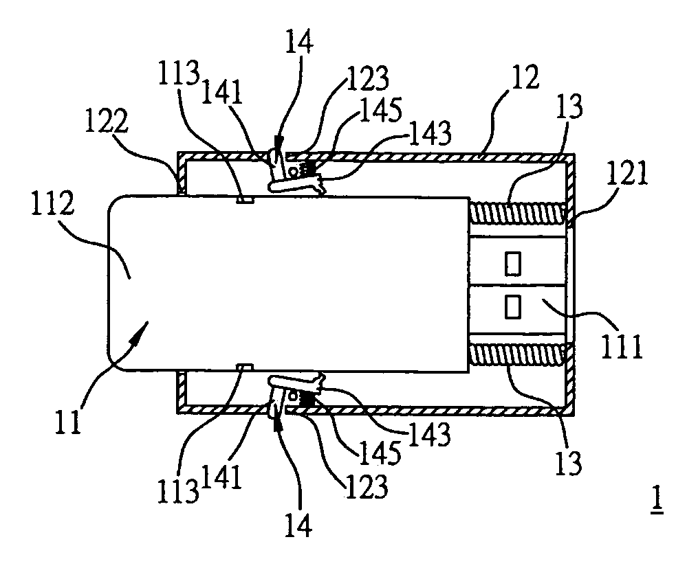
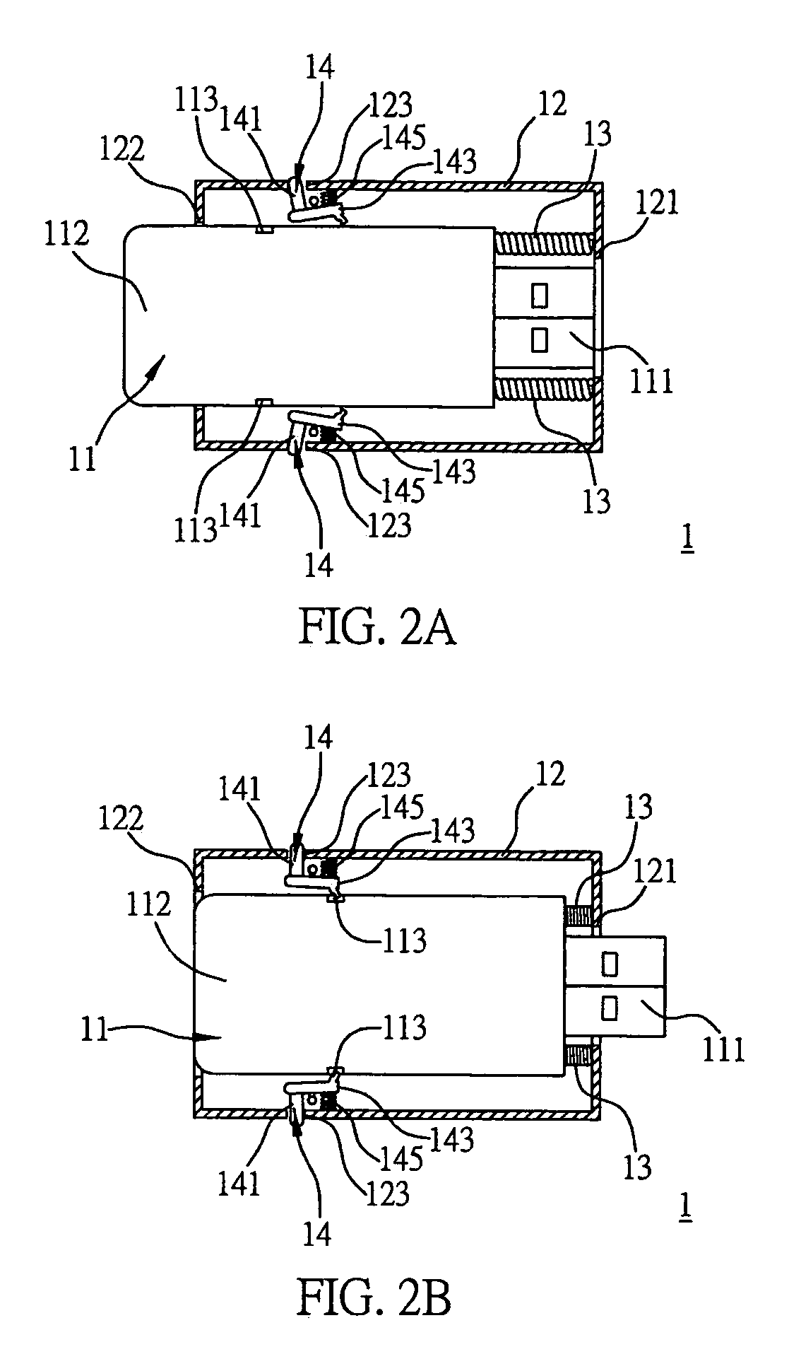
[0012]The electronic device of the present invention preferably comprises two positioning components, which are mounted symmetrically to an axis of the sheath. This arrangement allows the main body to be more firmly fixed in position and to slide more smoothly. If it is to release the main body from the fixing position, the user only needs to use the thumb and forefinger of one hand to operate the pressing portion of each of the positioning components.
[0014]As concluded from the above description, whether the user wishes to use or store the electronic device of the present invention, he / she can easily accomplish it by only using one hand. Further, as the electronic device itself has the sheath for protecting the connection portion, the sheath would not be lost unlike the protective cover of the prior art. Moreover, when it is to use the electronic device, the user presses the tail portion of the main body without touching the connection portion of the main body, thereby preventing the connection portion from being contaminated or damaged.

Problems solved by technology

As there is a need to store more and more data in the form of music and picture files, conventional data storage devices are no longer suitable as not having sufficient data storage capacity.
Since the USB storage device is connected via a connection portion thereof (i.e. the USB connector) to an external device such as a computer to perform data transmission, if the USB connector is damaged due to external force or impact, the performance of the USB storage device would be adversely affected.
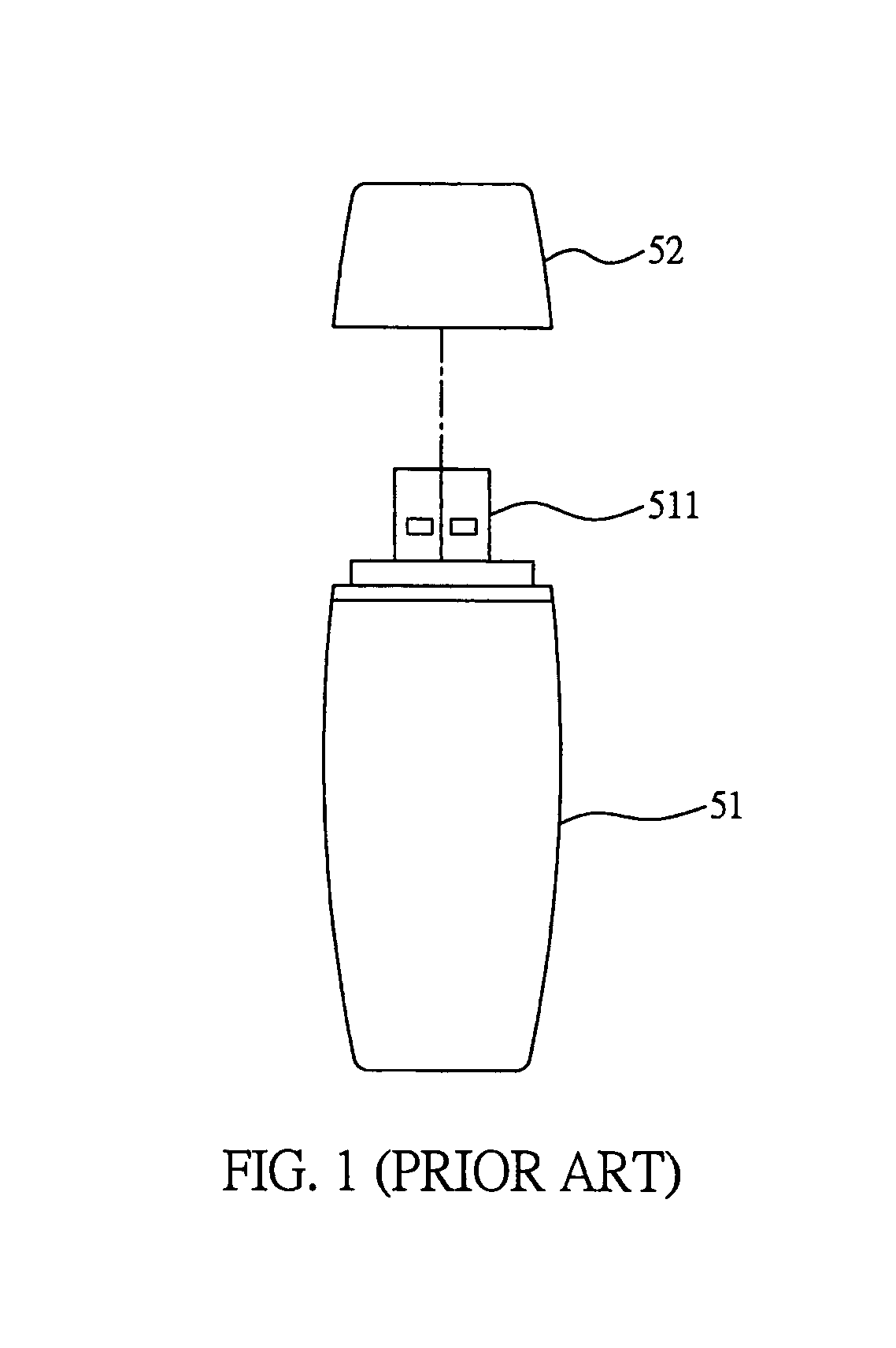
However, during the practical application, as the protective cover 52 must be removed in order to use the USB storage device 51, the protective cover 52 is easily lost, making the connection portion 511 fail to be protected and thereby reducing the lifetime of the USB storage device 51.
Therefore, the problem to be solved here is to provide an electronic device itself having a sheath structure, without having to use a detachable protective cover to protect a connection portion of the electronic device.

Method used


Image

  • Electronic device with sheath structure
  • Electronic device with sheath structure
  • Electronic device with sheath structure

Examples


Embodiment Construction

[0019]Preferred embodiments of an electronic device with a sheath structure as proposed in the present invention are described as follows with reference to FIGS. 2A and 2B. The drawings are simplified schematic diagrams and merely illustrate the components pertaining to the invention, and the arrangement of components could be modified as required in practice.

[0020]FIG. 2A is a cross-sectional view of the electronic device 1 being stored according to the present invention. FIG. 2B is a cross-sectional view of the electronic device 1 in use. As shown in FIGS. 2A and 2B, the electronic device 1 can be a USB storage device having a memory for storing data. The electronic device 1 comprises a main body 11 having a connection portion 111 consistent with USB specification at a terminal thereof, and a sheath 12 for the main body 11 to be slidably received therein. The sheath 12 comprises a first opening 121 and a second opening 122. Two first elastic components 13, such as compressed coils...


PUM


Abstract

An electronic device includes a main body having a connection portion for electrically connecting the electronic device to an external device; a sheath for the main body to be slidably received therein; at least one positioning component provided in the sheath, for fixing the main body when the main body is sliding toward a first terminal of the sheath and arrives at a fixing position such that the connection portion is protruded from a first opening formed at the first terminal in order to use the electronic device; and at least one first elastic component provided in the sheath, for pressing the main body to move toward a second terminal of the sheath when the main body is released from the fixing position and is sliding toward the first terminal of the sheath, such that the connection portion is received in the sheath in order to store the electronic device.

Description

FIELD OF THE INVENTION[0001]The present invention relates to electronic devices with sheath structures, and more particularly, to an electronic device with a sheath structure for protecting a connection portion of the electronic device.BACKGROUND OF THE INVENTION[0002]Various computer peripheral devices have been developed in response to the progress of computer information industry. In order to facilitate data sharing and transmission between computer information products, the peripheral devices such as CD-ROM driver, printer, scanner, mobile storage device and so on are externally connected to computers by means of connectors having common connecting interface consistent with Universal Serial Bus (USB) specification or IEEE (Institute of Electrical and Electronics Engineers) 1394 specification, etc. The USB connecting interface has become the important connecting interface for the peripheral devices because it has a much higher transmission rate than that of parallel ports or seri...

Claims


Application Information

Patent Timeline
IPC IPC(8): H01R13/44H01R13/60G06F1/16H01R13/453H01R13/627H01R13/635
CPCH01R13/4538H01R13/635H01R13/6275H01R13/60
Inventor SHE, YU-MINLEE, ING-HAU
Owner INVENTEC CORP
Learn More