Fixing structure for battery

a fixing structure and battery technology, applied in the direction of electrical apparatus construction details, cell components, cell component details, etc., can solve the problems of data loss, conventional battery fixing structure is not waterproof or dustproof, prior art has its drawbacks, etc., to prevent the battery from being released and permeating the liquid

Inactive Publication Date: 2011-03-31
ASKEY COMP
View PDF5 Cites 11 Cited by
  • Summary
  • Abstract
  • Description
  • Claims
  • Application Information

AI Technical Summary

Benefits of technology

[0012]Unlike the prior art, the present invention discloses encapsulating a connecting portion with a waterproof element and disposing a plug element on a casing to prevent a liquid, such as water, from permeating into the connecting portion and thus create a short circuit or cause damage to a component inside an electronic device. Hence, the present invention improves on the prior art by preventing permeation of a liquid. Also, a locking portion is provided on one side of a battery, and an engaging portion is provided on the other side of the battery and thus opposite the locking portion; in so doing, the present invention provides multiple means of positioning and thus is effective in preventing the battery from being released from a receiving portion of an electronic device when the electronic device drops inadvertently, which might otherwise create a short circuit or result in data loss.

Problems solved by technology

With industrial environments being typically adverse, sometimes mobile computers (UMPC) have to be used in the humid and dusty environment.
However, the prior art does have its drawbacks.
The conventional battery fixing structure is not waterproof or dustproof.
The portable electronic device 1 is compact and thus likely to be dropped inadvertently; in consequence, the battery 13 is ejected out from the receiving space 10, as a result, the power interruption leads to loss of data.
However, the battery fixing technique is not free of a drawback either.
The battery fixing structure enables the battery to be firmly fixed in position to the receiving space and yet renders installation and uninstalling of the battery inconvenient.

Method used


Image

  • Fixing structure for battery
  • Fixing structure for battery
  • Fixing structure for battery

Examples


Embodiment Construction

[0018]The way of implementing the present invention is hereunder illustrated with a specific embodiment to enable persons skilled in the art to readily gain insight into the other advantages and effects of the present invention with references made to the disclosure contained in the specification.

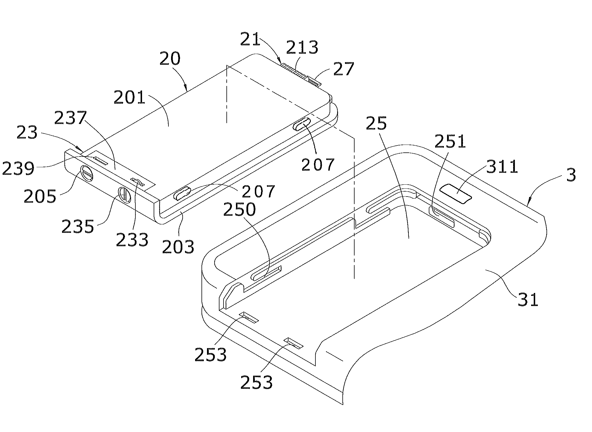
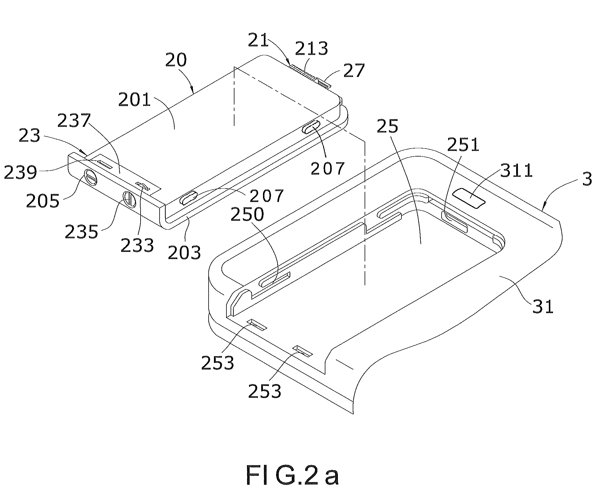
[0019]Referring to FIG. 2a through FIG. 3b, there are shown schematic views of a preferred embodiment according to the present invention. Referring to FIG. 2a, a fixing structure for a battery according to the present invention enables a battery 20 to be fixed in position to a casing 31 of an electronic device 3. The fixing structure for the battery 20 comprises a connecting portion 21, a locking portion 23, and a receiving portion 25. The connecting portion 21 and the locking portion 23 are provided on opposite sides of the battery 20 respectively. The receiving portion 25 is provided on the casing 31. In this embodiment, the battery 20 further comprises a battery body 201 and a covering p...


PUM

PropertyMeasurementUnit
permeationaaaaaaaaaa
electric poweraaaaaaaaaa
waterproofaaaaaaaaaa

Abstract

A fixing structure for a battery positions the battery in a casing of an electronic device. The fixing structure includes at least a connecting portion, at least a locking portion, and a receiving portion. The connecting portion is on one side of the battery and with a waterproof element. The locking portion is on the other side of the battery and is opposite to the connecting portion. The receiving portion is on the casing and with a first inserting portion and a plurality of second inserting portions. The first inserting portion and the second inserting portions correspond in position to the connecting portion and the locking portion respectively. Hence, the fixing structure protects the electronic device against permeation of water and ensures secure positioning of the battery.

Description

CROSS-REFERENCE TO RELATED APPLICATIONS[0001]This non-provisional application claims priority under 35 U.S.C. §119(a) on Patent Application No(s). 098217789 filed in Taiwan, R.O.C. on 25 Sep. 2009, the entire contents of which are hereby incorporated by reference.FIELD OF THE INVENTION[0002]The present invention relates to battery fixing technology, and more particularly, to a fixing structure for a battery.BACKGROUND OF THE INVENTION[0003]Portable electronic devices are not only compact and convenient to carry but also feature special human-machine interfaces (such as touch control input interfaces), wireless communication (such as voice and data transmission), or artificial intelligence (such as text and voice recognition) and thus are widely used in daily life. Portable electronic devices are in wide use including mobile computers (ultra mobile personal computer, UMPC), interpreters, personal digital assistants (PDA), notebook computers, video players, and handheld game consoles[...

Claims


Application Information

Patent Timeline
Patent Type & Authority Applications(United States)
IPC IPC(8): H05K7/00H01M50/202H01M50/209H01M50/247H01M50/264
CPCH01M2/1066H04M1/18H04M1/0262Y02E60/10H01M50/209H01M50/264H01M50/247H01M50/202
Inventor CHANG, CHING-HUIHSIEH, CHING-FENGLEE, KO-HSIEN
Owner ASKEY COMP
Why Eureka
Try Eureka