Resin molded product and method for producing same

a technology of resin molded products and molding resins, which is applied in the direction of coupling device details, coupling device connections, electrical devices, etc., can solve the problems of resin leakage, resin leakage, and the inability of the resin portion to be set in the mold, so as to reduce the reliability of connection between the mating conductor and the connecting portion, prevent resin leakage at the bend, and prevent the adhesion of molding resin to the connecting portion

Active Publication Date: 2021-04-08
SUMITOMO WIRING SYST LTD
View PDF0 Cites 0 Cited by
  • Summary
  • Abstract
  • Description
  • Claims
  • Application Information

AI Technical Summary

Benefits of technology

[0013]When the connecting portion is provided on the one end of the bend, the molding resin may adhere to a connection surface of the connecting portion and connection reliability between the mating conductor and the connecting portion may be reduced if resin leakage occurs at the bend. However, according to the above configuration, even if excess metal parts are formed on the side edges of the bend by bending substantially at a right angle, resin leakage at the bend can be prevented by forming the flat surfaces on the side edges of the bend and cutting off the resin between the flat surfaces and the mold. Thus, the adhesion of the molding resin to the connecting portion can be prevented. This is very effective when the bend is distorted by being bent by press working.
[0014]According to the teaching of this specification, resin leakage to an unintended part is prevented while it is enabled to set a metal plate material in a mold.

Problems solved by technology

Thus, if it is attempted to mold the connector housing by cutting off the molding resin at the position of the bend, the excess metal parts of the bend interfere with the mold, and the conductive plate cannot be set in the mold.
However, the width of the bend then is smaller than a predetermined width and the resin cannot be cut off at the position of the bend, thereby causing resin leakage.
For example, if the metal member is press-worked, there is a tendency that the resin portion cannot be set in a mold due to distortion of the sides of the metal member caused by press working.

Method used


Image

  • Resin molded product and method for producing same
  • Resin molded product and method for producing same
  • Resin molded product and method for producing same

Examples


Embodiment Construction

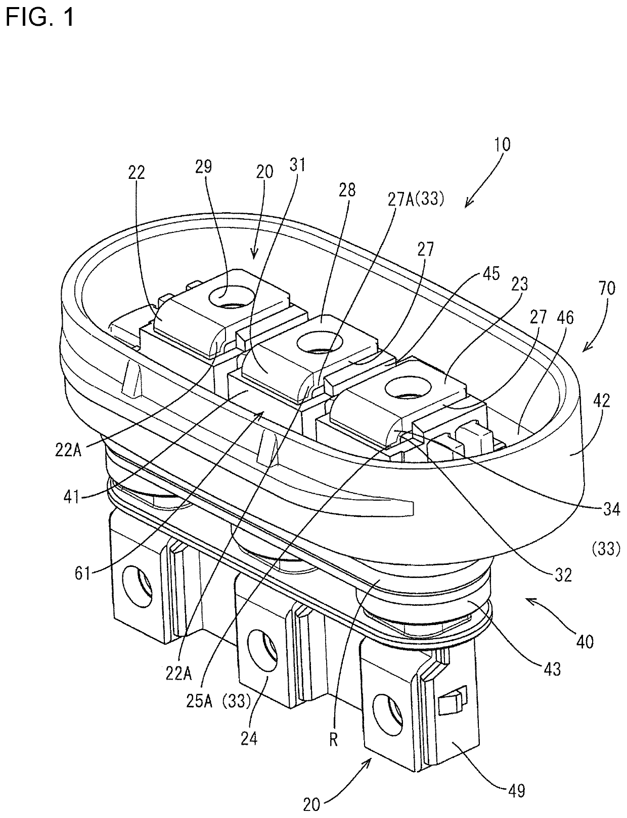
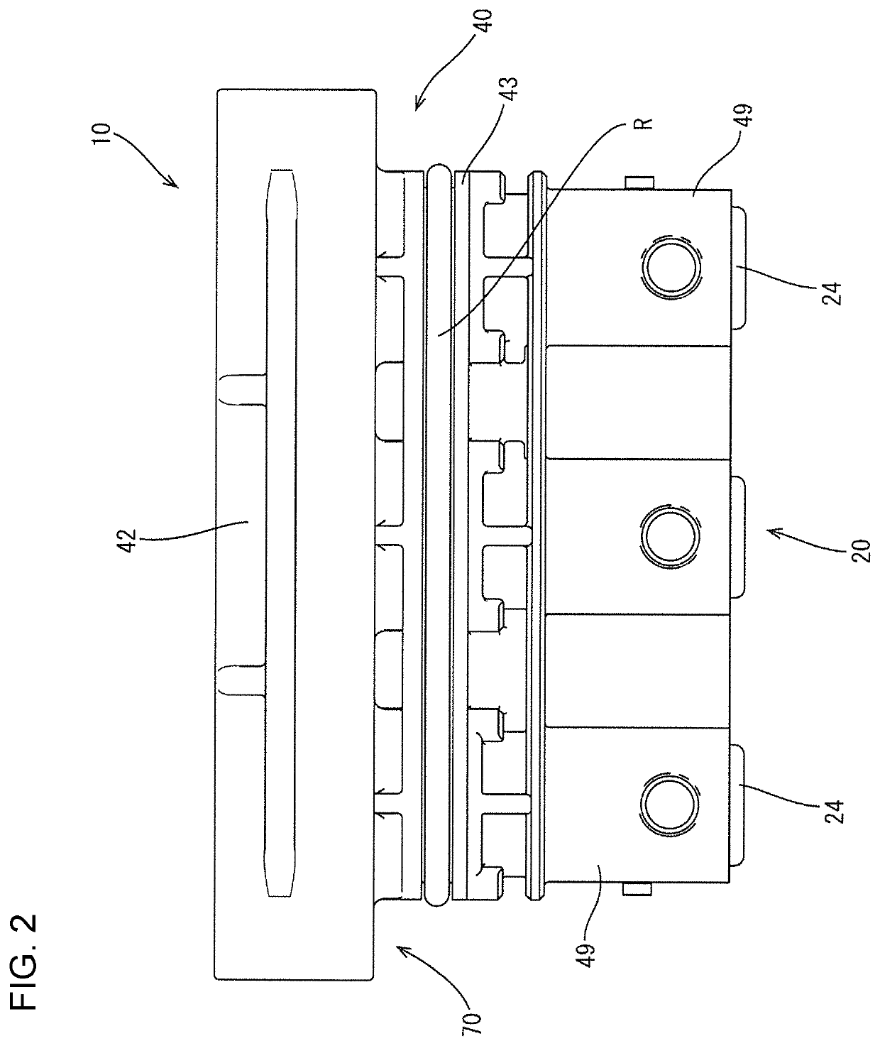
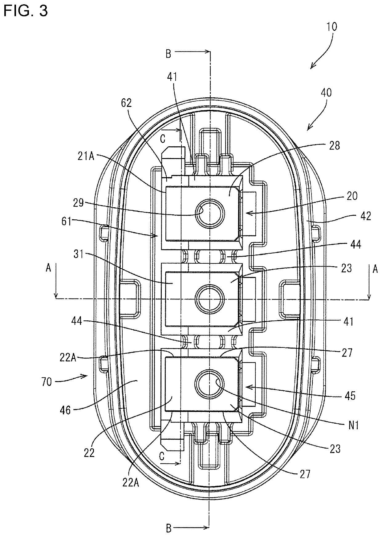
[0033]An embodiment is described with reference to FIGS. 1 to 18. A terminal block (an example of a “resin molded product”) 10 to be mounted on an unillustrated case of a device installed in a vehicle is illustrated in this embodiment, and the terminal block 10 is for joining unillustrated device-side terminals disposed in the case and unillustrated mating terminals (an example of a “mating conductor”) provided on an end of a wiring harness. Note that, in the following description, a lateral direction is based on a lateral direction in FIGS. 2 and 10 and a vertical direction is based on a vertical direction in FIGS. 2 and 10. Further, a front-rear direction is based on a lateral direction in FIGS. 5, 11 and 17, wherein a shown left side is referred to as a front side and a shown right side is referred to as a rear side.

[0034]As shown in FIGS. 1 to 7, the terminal block 10 includes three terminals (an example of a “metal member”) 20, and a housing (an example of a “resin portion”) 40...


PUM

PropertyMeasurementUnit
thicknessaaaaaaaaaa
angleaaaaaaaaaa
conductiveaaaaaaaaaa

Abstract

A resin molded product is a terminal body 10 in which plate-like terminals 20 and a housing 40 made of synthetic resin are integrally fixed and includes bent portions 22 provided substantially at a right angle by press-working the terminals 20, molded portions 62 provided in the housing 40 to embed and cover inner curved surfaces 30 of the bent portions 22 obliquely from a lower-rear side, flat surface portions 32 provided in the form of flat surfaces on inner peripheral edge parts of side parts 22A of the bent portion 22 and disposed adjacent to the molded portions to be exposed from the molded portions, and thinned portions 34 made thinner than the flat surface portions 32 on the side parts 22A.

Description

BACKGROUND[0001]Field of the Invention. This specification relates to a resin molded product and a method for producing the same.[0002]Description of the Related Art. Japanese Unexamined Patent Publication No. 2012-195067 discloses a terminal block formed to fix an L-shaped conductive plate integrally to a connector housing made of synthetic resin.[0003]In assembling this terminal block, the conductive plate initially is bent into an L shape by stamping and bending a metal plate material by press working. The conductive plate then is set in a mold and molding resin is poured into the mold to form a primary molded product. Secondary molding then is carried out using this primary molded product as a core to mold the connector housing.[0004]If the conductive plate is made thicker in the above-described terminal block, excess metal bulges out on both widthwise sides of the bend when forming the bend. Thus, if it is attempted to mold the connector housing by cutting off the molding resin...

Claims


Application Information

Patent Timeline
Patent Type & Authority Applications(United States)
IPC IPC(8): H01R43/24H01R9/16H01R9/24
CPCH01R43/24H01R9/24H01R9/16H01R13/405B29C45/14
Inventor SAKAKURA, KOUJIKOBAYASHI, YUTAKA
Owner SUMITOMO WIRING SYST LTD
Why Eureka
Try Eureka