Bite type tube connection structure, tube fitting, valve, closing valve, refrigerating cycle device, hot-water supply device, bite type tube connection method, and on-site tube connection method

a tube connection and onsite technology, applied in the field of bite-type tube connection structure and tube fitting, to achieve the effect of preventing leakage from the tube connection portion, increasing ease of work, and increasing ease of work

Inactive Publication Date: 2009-02-19
DAIKIN IND LTD
View PDF32 Cites 16 Cited by
  • Summary
  • Abstract
  • Description
  • Claims
  • Application Information

AI Technical Summary

Benefits of technology

[0040]According to this method, the primary deforming portion of the bite type sleeve bites into the connection tube, or the primary deforming portion can be inserted between the fitting main body and the connection tube in a wedge-like fashion through the first pressing force applied when the fastening nut is fastened by hand. As a result, the connection tube can be held in a predetermined location. Accordingly, it becomes unnecessary to hold the connection tube in a predetermined location when the fastening nut is fastened using a fastening tool, and the ease of work increases a great deal.
[0041]In order to solve the above described problem, an eighth aspect of the present invention provides an on-site tube connection method to which the above described bite type tube connection method is applied. In this case, leakage from the tube connection portion is prevented when tube assembly is carried out on-site, and therefore, the ease of work increases.

Problems solved by technology

This problem arises in the same manner with tube fittings used for any device other than the refrigerating cycle device of air conditioners and the like.

Method used


Image

  • Bite type tube connection structure, tube fitting, valve, closing valve, refrigerating cycle device, hot-water supply device, bite type tube connection method, and on-site tube connection method
  • Bite type tube connection structure, tube fitting, valve, closing valve, refrigerating cycle device, hot-water supply device, bite type tube connection method, and on-site tube connection method
  • Bite type tube connection structure, tube fitting, valve, closing valve, refrigerating cycle device, hot-water supply device, bite type tube connection method, and on-site tube connection method

Examples


first embodiment

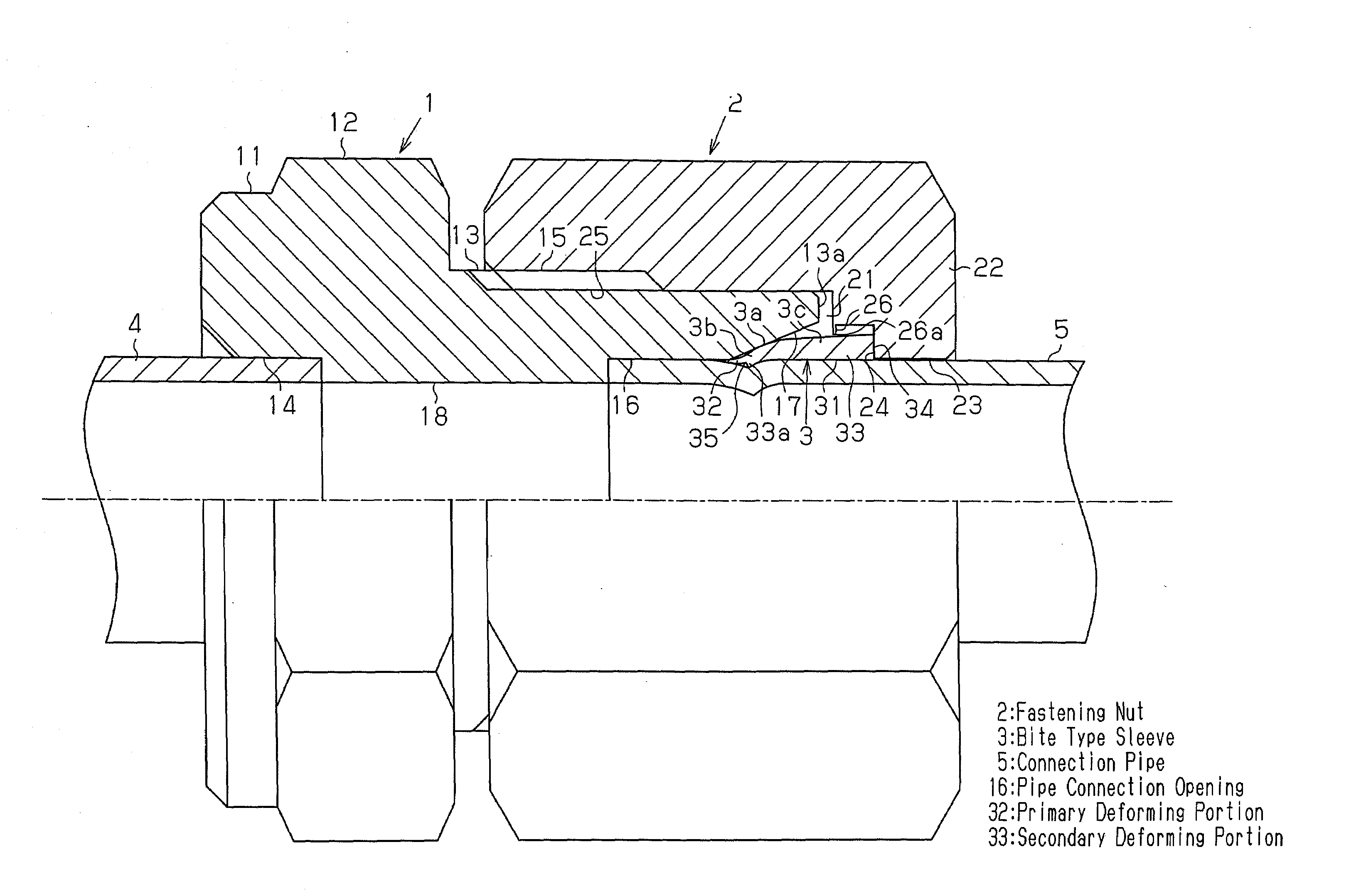
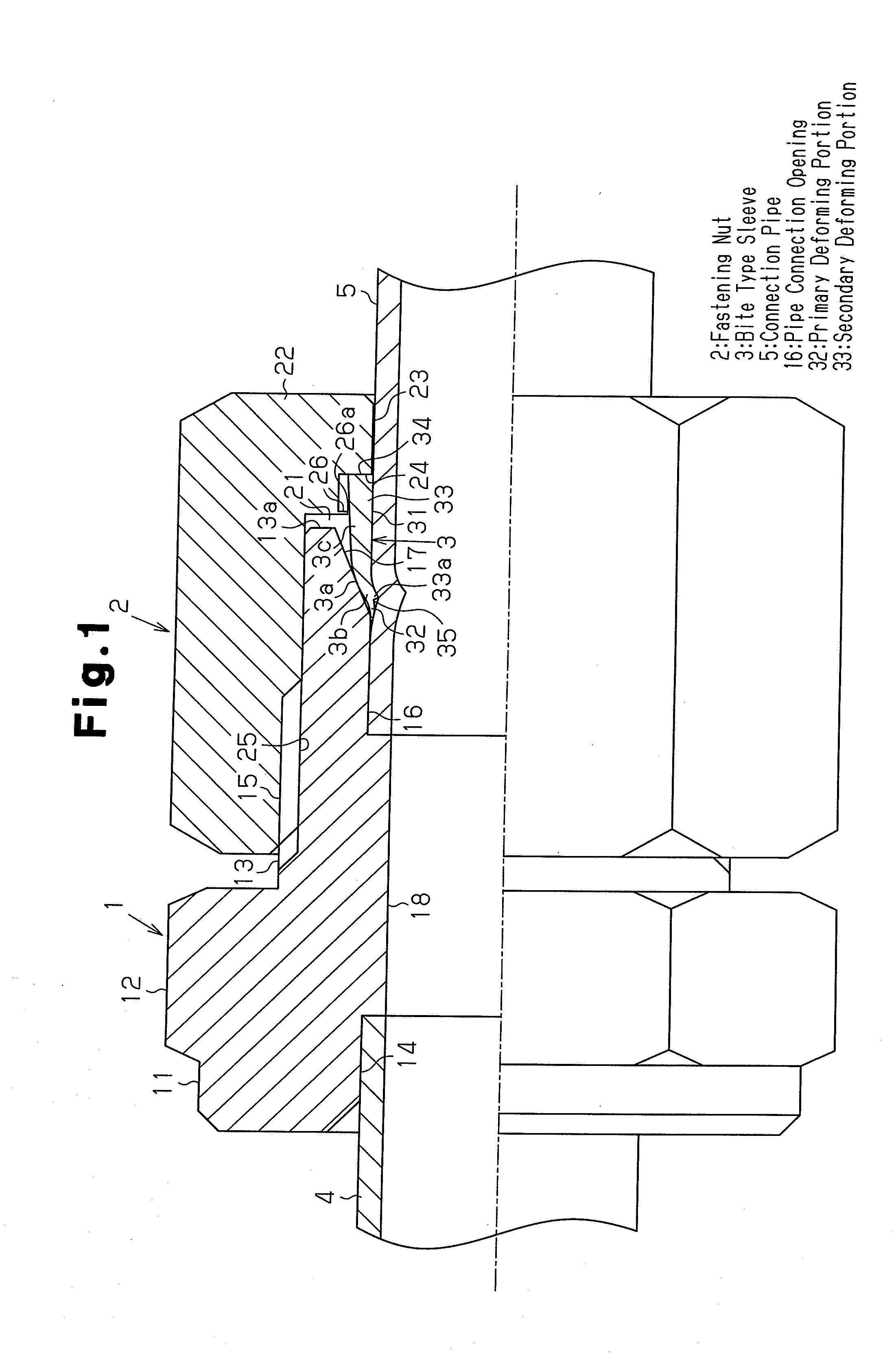
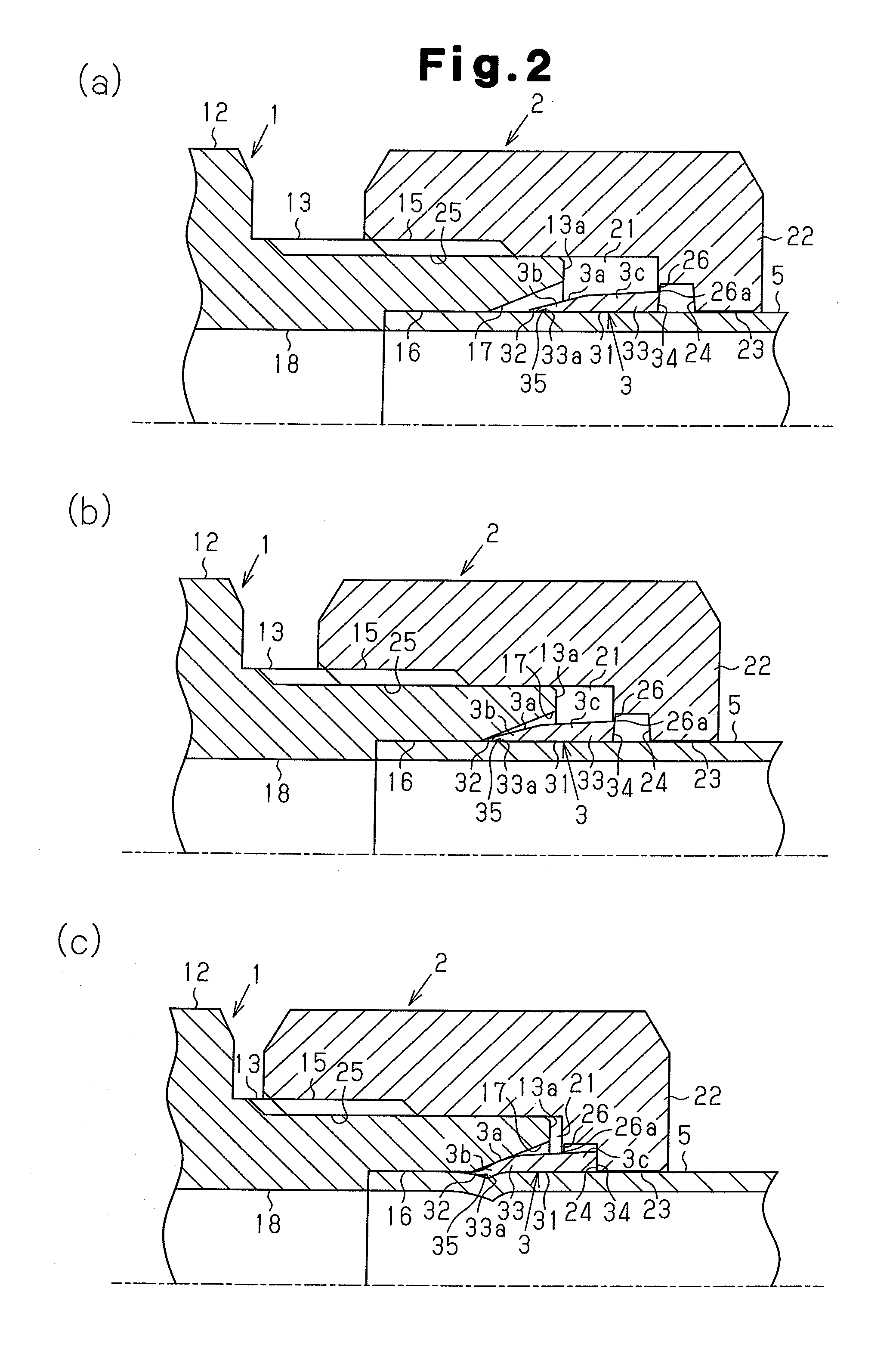
[0061]In the following, a bite type tube fitting having a bite type tube connection structure according to a first embodiment of the present invention is described in reference to FIGS. 1 to 5.

[0062]As shown in FIGS. 1 to 3, the bite type tube fitting according to the present embodiment is a tube fitting for connecting refrigerant tubes made of copper for a refrigerant cycle device. The bite type tube connection structure according to the present invention is used in a tube connection portion in which a tube is removably connected. The bite type tube fitting is made of a copper alloy having a higher hardness than copper tubes. The bite type tube fitting is provided with a main body of a fitting 1, a fastening nut 2, which is a fastening part, and a bite type sleeve 3 in cylindrical form. In the bite type tube fitting, a fixed tube 4 made of copper is connected to the proximal end of the fitting main body 1, that is to say, the end portion on the side opposite to the fastening nut 2....

second embodiment

[0092]Next, a bite type tube connection structure according to a second embodiment and a bite type tube fitting using the same are described in reference to FIG. 6. In the second embodiment, detailed descriptions of portions which are the same as in the first embodiment are omitted.

[0093]In the second embodiment, the bite type sleeve 3 is separate from the fastening nut 2 and the fitting main body 1. Therefore, the fitting main body 1 has exactly the same configuration as in the first embodiment. In addition, the second embodiment is different from the first embodiment in that the thin linking portion 26 shown in FIG. 5 is omitted and the bite type sleeve 3 has a divided structure. In the following, the respective components are compared with those in the first embodiment.

[0094]As shown in FIG. 6, the fitting main body 1 has a socket portion 11 (see FIG. 1), a nut portion 12, and a tube connection portion 13.

[0095]The bite type sleeve 3 is placed in the space 21 within the fastening...

third embodiment

[0105]Next, a bite type tube connection structure according to a third embodiment and a bite type tube fitting using the same are described in reference to FIG. 7. In the third embodiment, detailed descriptions for portions which are the same as in the first embodiment are omitted.

[0106]In the third embodiment, the bite type sleeve 3 is integrated with the fitting main body 1. That is to say, the bite type sleeve 3, which is a separate part, is adhered to the fitting main body 1. Therefore, the fitting main body 1 and the fastening nut 2 have a configuration which is partially different from that of the first embodiment.

[0107]As shown in FIG. 7, the fitting main body 1 has a socket portion 11 (see FIG. 1), a nut portion 12, and a tube connection portion 13. The socket portion 11 and the nut portion 12 are the same as in the first embodiment. The tube connection portion 13 has an external thread 15, a tube connection opening 16, a tapered guiding surface 17, and a communicating hole ...


PUM


Abstract

A fitting has a bite type tube connection structure with a bite type sleeve in cylindrical form. The bite type sleeve is formed of a primary deforming portion and a secondary deforming portion. The primary deforming portion bites into a connection tube 5 or is inserted between the fitting main body and the connection tube in a wedge-like fashion as a result of a first pressing force in the axial direction applied when a fastening nut is fastened. The secondary deforming portion is deformed by a second pressing force in the axial direction applied when the fastening nut is fastened and greater than the first pressing force. When the primary deforming portion bites into the connection tube, the connection tube is temporarily held against the fitting main body. Then, the fastening operation is completed by fastening the fastening nut.

Description

TECHNICAL FIELD[0001]The present invention relates to a bite type tube connection structure and a tube fitting, a valve, a closing valve, a refrigerating cycle device, a hot-water supply device, a bite type tube connection method and an on-site tube connection method, each of which uses this bite type tube connection structure. In particular, the present invention relates to an increase in the ease of work in the case where a bite type tube connection structure is adopted.BACKGROUND ART[0002]In general, tube fittings are removable so that tubes for fluid can be easily replaced and repaired. Tube fittings have a variety of structures in accordance with applications.[0003]In the refrigerating cycle device of conventional air conditioners, for example, flair type tube fittings have been used as tube fittings. From the point of view of environmental protection in recent years, hydrocarbon (HC) refrigerants such as propane, ethane, ethylene, n-pentane, n-butane and isobutane, each of whi...

Claims


Application Information

Patent Timeline
Patent Type & Authority Applications(United States)
IPC IPC(8): F16L19/08
CPCF16L19/103F16L19/14F16L19/10F25B2345/006F25B41/003F25B41/40F16L19/08F25B41/00F25B1/00
Inventor NAKATA, HARUONAKAYA, TSUKASASHIMAMURA, TAKASHI
Owner DAIKIN IND LTD
Why Eureka
Try Eureka