
Low insertion force grommet

Inactive Publication Date: 2006-09-12
YAZAKI NORTH AMERICA
View PDF5 Cites 31 Cited by
  • Summary
  • Abstract
  • Description
  • Claims
  • Application Information

AI Technical Summary

Benefits of technology

[0008]Accordingly, it is an object of this invention to lower the insertion force necessary to properly install a grommet on a vehicle panel by providing friction-reducing contact elements to a grommet engagement surface.
[0010]A further object of the invention is to enable the grommet to easily compress during insertion and to keep softer material of the grommet from contacting an edge of a panel aperture by placing recesses in the engagement surface between the contact elements.
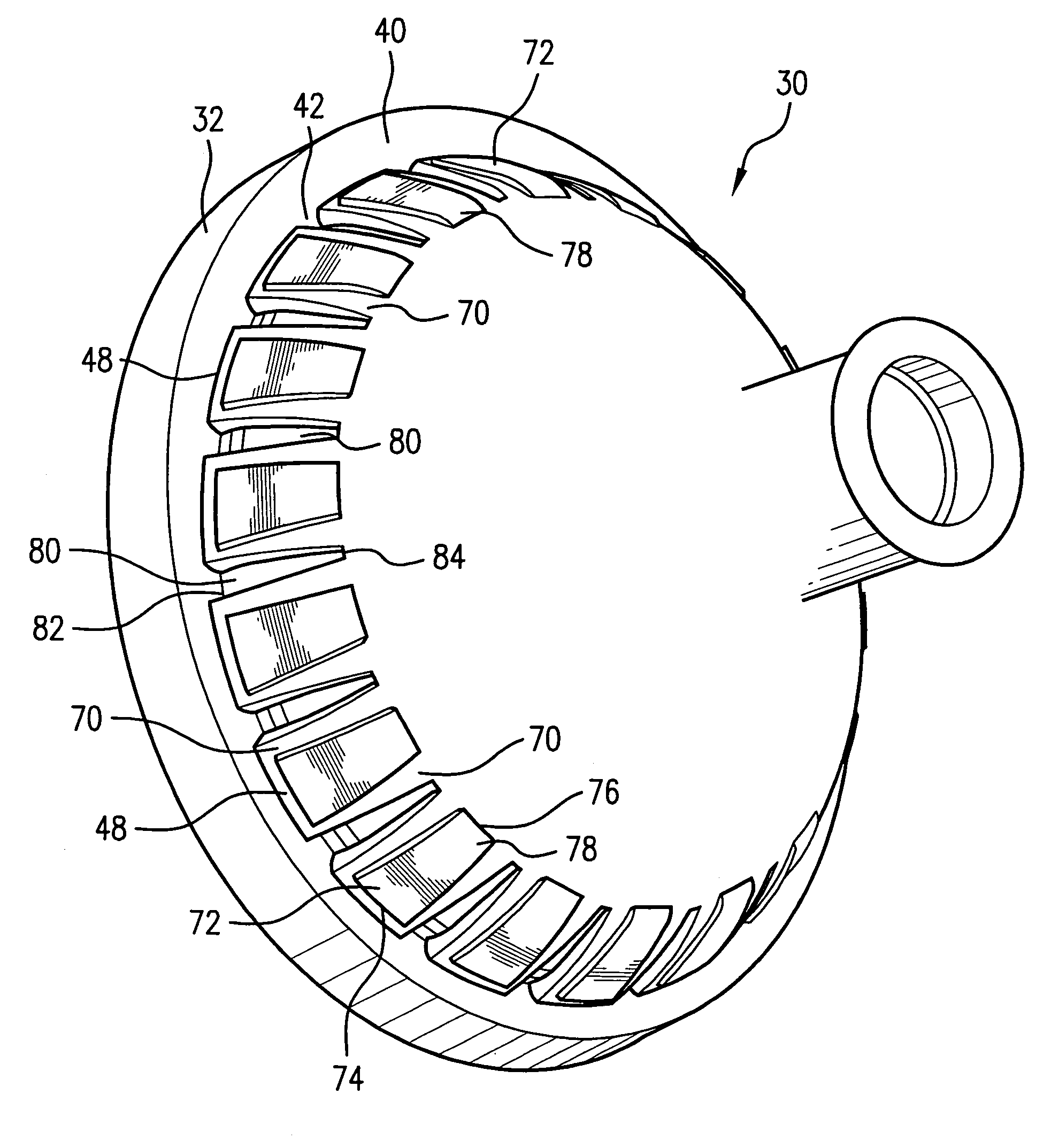
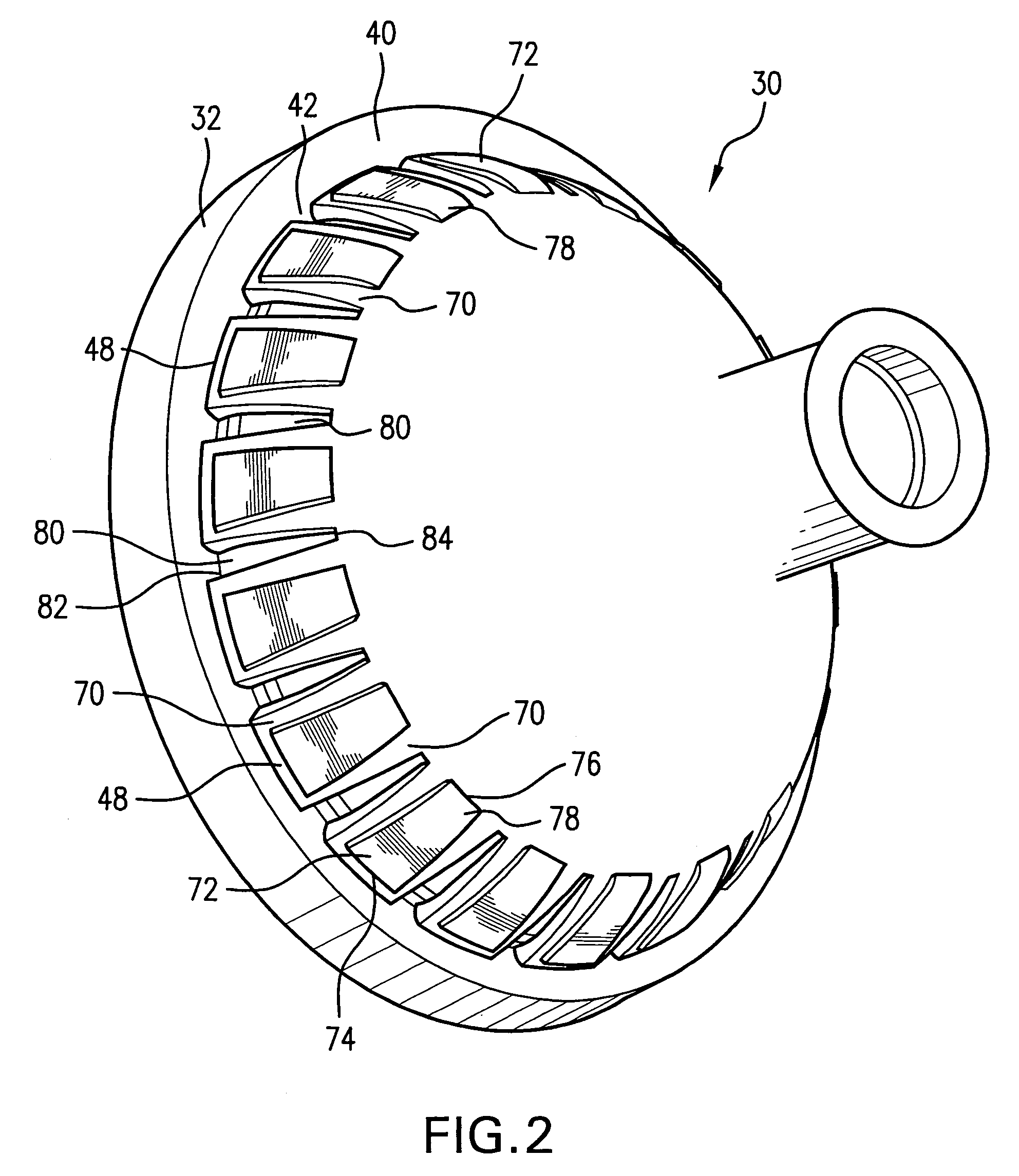
[0011]In carrying out this invention in the illustrative embodiment thereof, a grommet mostly made of a soft pliable material has a generally conical section with an engagement surface or region that contacts the edge of the panel aperture during insertion of the grommet. Raised, hard, plastic contact pads are molded onto the engagement region. The contact pads are circumferentially spaced in a row around the grommet, allowing the grommet to remain flexible. Relief cuts or recesses are provided between the contact pads to keep softer material of the grommet from contacting the edge of the aperture and further enhance the ability of the grommet to compress during insertion. The hard plastic slides into and through the aperture more easily than a softer surface of the grommet.

Problems solved by technology

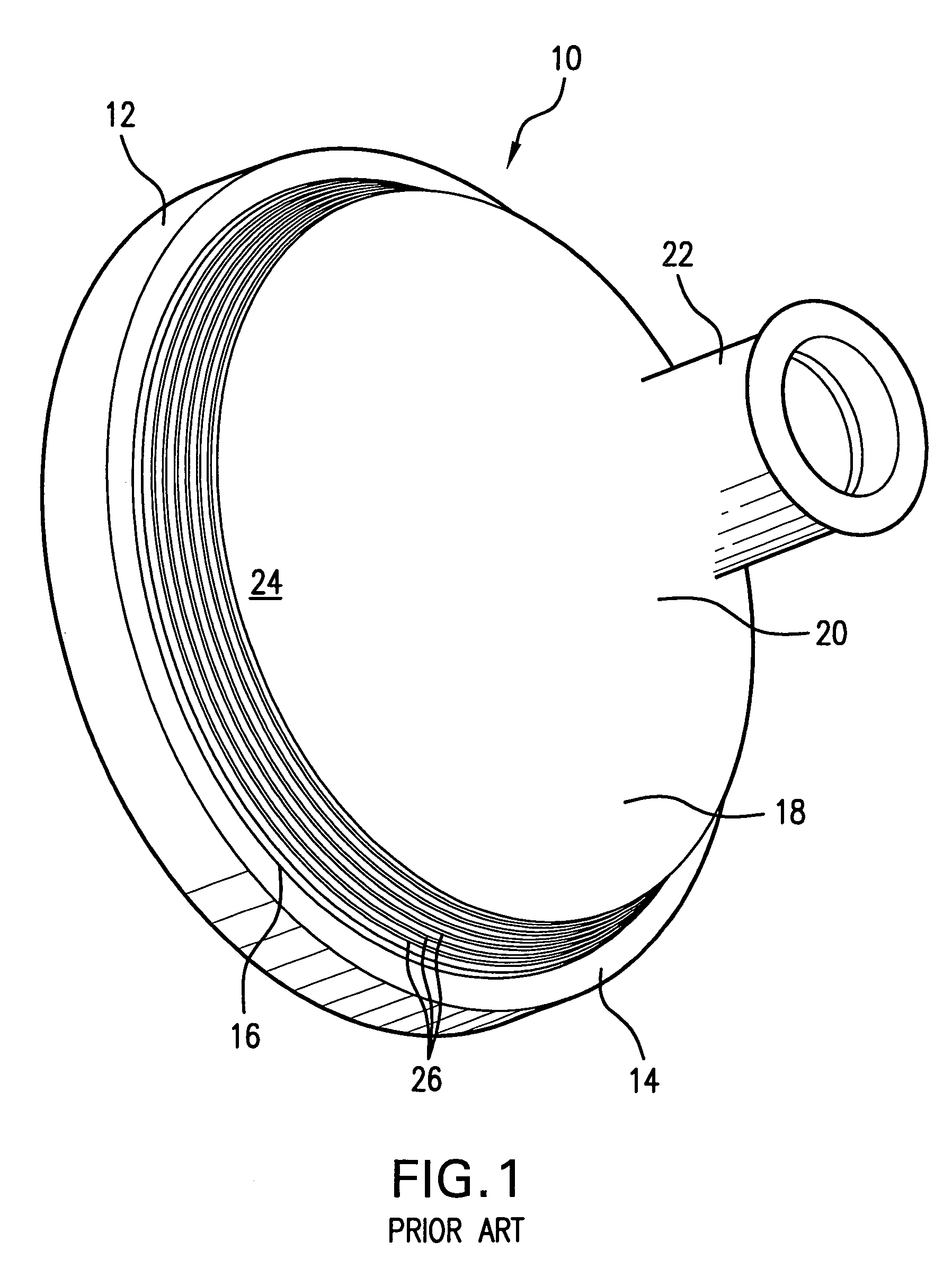
Typical grommets have historically been difficult to install in vehicle bulkhead or panel apertures because of the high friction arising between an interface region or engagement surface of the grommet and an edge or edges of the aperture during insertion.
The edge of the aperture tends to bite or dig into the rubber, making it difficult to slide the grommet into the sealing position.
The lubricant often spreads to other vehicle locations and parts, and can foul the assembly area.
However, these ridges 26 can catch on the sheet metal of the panel and often make it difficult to know when the grommet 10 is seated properly.

Method used


Image

  • Low insertion force grommet
  • Low insertion force grommet
  • Low insertion force grommet

Examples


Embodiment Construction

[0018]Referring now to FIGS. 2 and 3, a grommet 30 according to the present invention is illustrated. The grommet has a main part with a first, generally circular locking or flange section 32. An opening 34 into an interior 36 of the grommet 30 is surrounded by a first side 38 of the flange section 32. A second, opposite, sealing side 40 of the flange section 32 forms one side wall of a groove 42 extending around the grommet. The groove 42 has an opposite, shorter side wall 44 and a bottom wall 46. The shorter side wall 44 is at a first, wider end 48 of a second, generally conical section 50 that tapers or converges to a second, narrower end 52. The conical section 50 has an inner surface 54 facing the interior 36 of the grommet 30. An internal harness enclosure wall 56 extends into the interior 36 from the inner surface 54, converging to an entrance 58 near the flange section opening 34. The second end 52 of the conical section 50 is integral with a third, hollow, tubular section 6...


PUM


Abstract

A grommet mainly made of soft, pliable material has a flange section for sealing against a first side of a vehicle panel around an aperture through the panel. A groove separates the flange section from a conical section that tapers from the groove to a narrower tubular section for tightly fitting around a wire harness passed through the grommet. The conical section has a wider end adjacent the groove that presses against a second, opposite side of the panel when the groove receives an edge of the aperture and the grommet is seated on the panel. The conical section has a region that engages the edge of the aperture as the grommet is pulled to an installed position. A plurality of raised, hard, rigid contact pads are arranged in a circumferential row around the engagement region to provide low friction while sliding past the edge of the aperture when the grommet is pulled through the aperture. The contact pads are spaced apart by recesses that maintain the compressibility of the grommet and keep the soft grommet material between the pads from contacting the edge of the aperture during installation. Angled tabs extend from undersides of the contact pads to help secure the pads on the grommet. The contact pads are connected by a ring structure embedded in the conical section.

Description

BACKGROUND OF THE INVENTION[0001]1. Field of the Invention[0002]The invention relates in general to grommets for routing wire harnesses through vehicle panel apertures and more particularly to a grommet having a raised, rigid material on an insertion engagement surface for lowering the force required to mount the grommet in the aperture.[0003]2. Discussion of Related Art[0004]Typical grommets have historically been difficult to install in vehicle bulkhead or panel apertures because of the high friction arising between an interface region or engagement surface of the grommet and an edge or edges of the aperture during insertion. The vehicle panel is usually made of sheet metal and the grommets often made of soft rubber. The edge of the aperture tends to bite or dig into the rubber, making it difficult to slide the grommet into the sealing position. Various methods have been used to reduce the force required to mount a grommet in an aperture of the panel through which a wire harness i...

Claims


Application Information

Patent Timeline
IPC IPC(8): H02G3/18
CPCB60R16/0222H02G3/22Y10T16/05
Inventor DUHR, JEROME ADAM DAVID
Owner YAZAKI NORTH AMERICA
Learn More