Electrical contact technology and methodology for the manufacture of large-diameter electrical slip rings

a technology of electrical contact and large-diameter, applied in the field of slip rings, can solve the problems of life and signal transfer, increase the cost of equipment used to electroplate precious metals on ring surfaces, and the cost of ring materials, as well as the costs associated, so as to achieve higher current density, run longer, and increase the speed of the rotor surface

Active Publication Date: 2006-09-12
MOOG INC
View PDF2 Cites 26 Cited by
  • Summary
  • Abstract
  • Description
  • Claims
  • Application Information

AI Technical Summary

Benefits of technology

[0024]Another object is to provide a first improvement in a high current density, long-life, high-speed slip ring, which improvement includes a collimator tube overlapping a portion of a brush tube and extending downwardly therefrom to limit lateral movement of a brush bundle when a rotor rotates.

Problems solved by technology

If the contacts have a long life requirement, then dust, wear debris and other contaminants may accumulate in the contact zone and create problems with life and signal transfer.
When manufacturing slip rings in the range of four to six feet in diameter, the costs of the ring material, as well as the costs associated with the equipment used to cast the dielectric material that supports the rings, the costs of equipment required to machine the support structure, and the costs of the equipment used to electroplate precious metal on a ring, rise dramatically if a continuous ring approach is used.
In this case, the dimensional tolerances that must be held for the ring I.D. and O.D. cause the continuous ring to be prohibitively expensive.
In addition, the bath required to electrodeposit metal on a six foot diameter ring is five to six times more expensive than that required for a 120° length of arc used to fabricate a segmented slip ring of the same diameter.
However, because of dimensional variations in the base O.D. and dimensional variations in the length of the strip used to form the conductive ring, the facing ring ends sometimes do not abut properly.
Thus, problems develop with electrical signal transmission.
Millions of ring revolutions may occur because these problems develop.

Method used


Image

  • Electrical contact technology and methodology for the manufacture of large-diameter electrical slip rings
  • Electrical contact technology and methodology for the manufacture of large-diameter electrical slip rings
  • Electrical contact technology and methodology for the manufacture of large-diameter electrical slip rings

Examples


Embodiment Construction

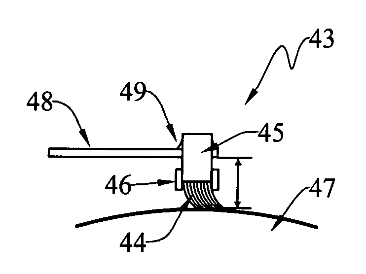
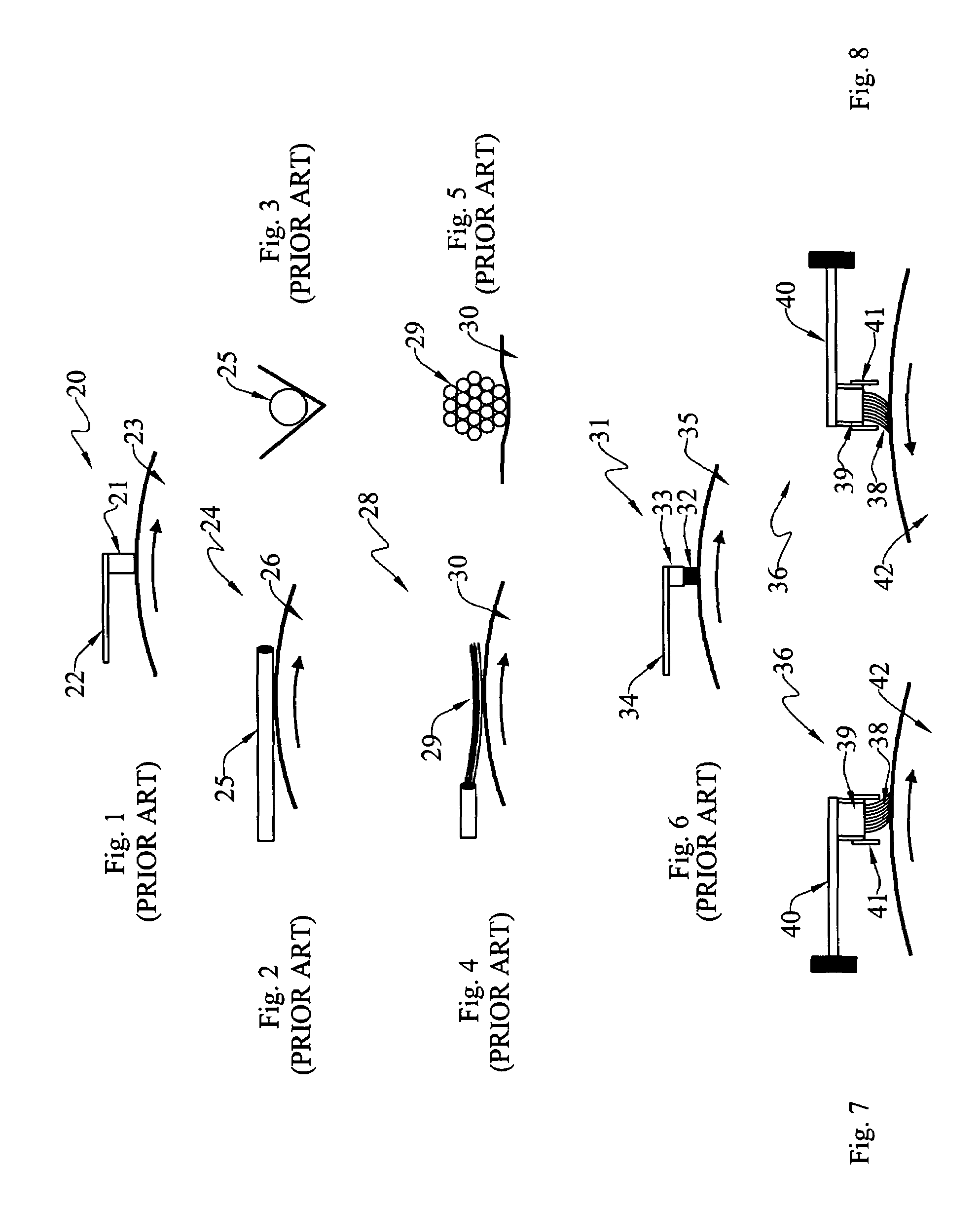
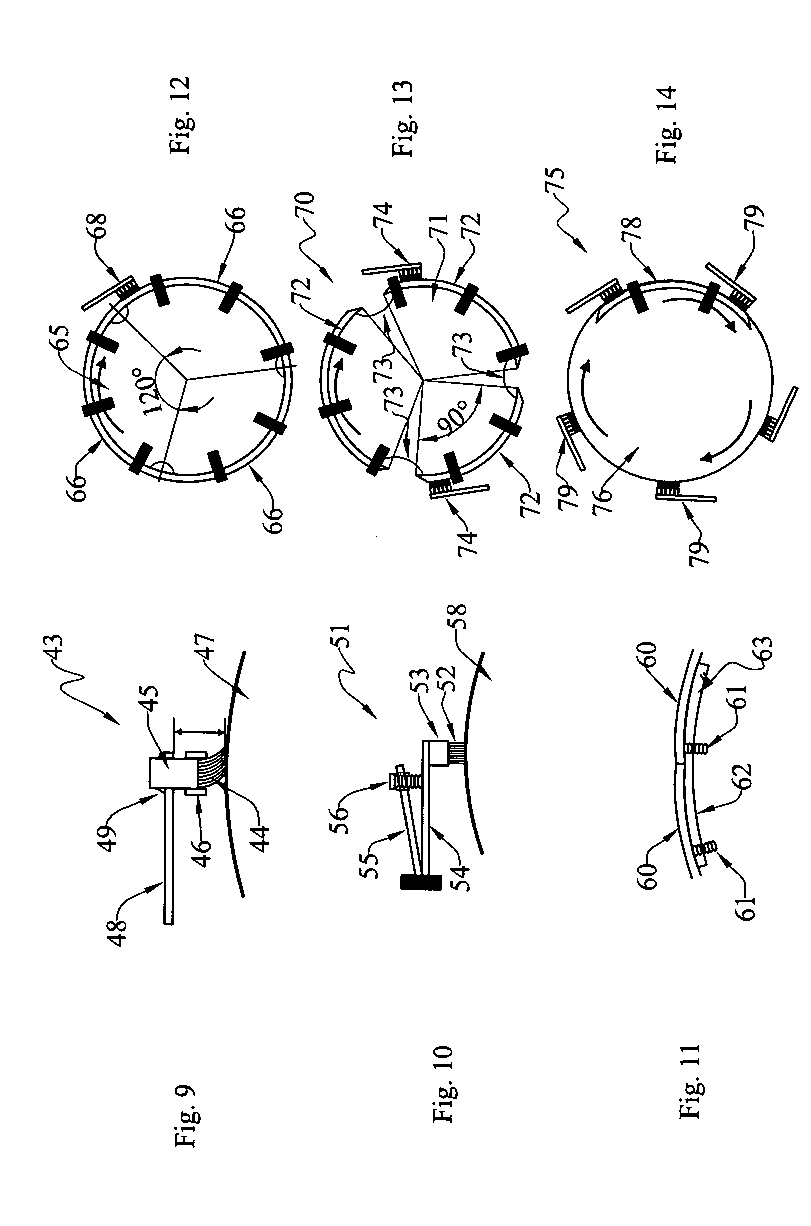
[0042]At the outset, it should be clearly understood that like reference numerals are intended to identify the same structural elements, portions or surfaces consistently throughout the several drawing figures, as such elements, portions or surfaces may be further described or explained by the entire written specification, of which this detailed description is an integral part. Unless otherwise indicated, the drawings are intended to be read (e.g., cross-hatching, arrangement of parts, proportion, degree, etc.) together with the specification, and are to be considered a portion of the entire written description of this invention. As used in the following description, the terms “horizontal”, “vertical”, “left”, “right”, “up” and “down”, as well as adjectival and adverbial derivatives thereof (e.g., “horizontally”, “rightwardly”, “upwardly”, etc.), simply refer to the orientation of the illustrated structure as the particular drawing figure faces the reader. Similarly, the terms “inwa...


PUM


Abstract

The present invention provides several improvements in a slip ring (36) that is adapted to provide electrical contact between a rotor (42) and stator (40). In one aspect, a brush tube (39) is crimped around the upper marginal end portions of a plurality of individual fibers (38) inserted therein. In another aspect, a collimator tube (41) extends downwardly beyond the end of the brush tube to limit lateral movement of the fibers in the bundle when the rotor rotates. In yet another arrangement, a spring (55, 56) is arranged to bear against a current-carrying conductor to adjustably vary the force by which the lower ends of the fibers are urged to move toward the rotor.

Description

TECHNICAL FIELD[0001]The present invention relates generally to slip rings for communicating electrical power and / or signal(s) between a rotor and stator, and, more particularly, to improvements in large-diameter slip rings that allow higher current densities, longer life, and higher rotor surface speeds to be achieved at lower costs than with current slip ring technology.BACKGROUND ART[0002]Electrical slip rings are used to transfer electrical power and / or signal(s) between a rotor and a stator. These devices are used in many different military and commercial applications, such as solar array drive mechanisms, aircraft and missile guidance platforms, undersea robots, CATSCAN systems, and the like. In some of these applications, slip rings are used in conjunction with other rotary components, such as torque motors, resolvers and encoders. Electrical slip rings must be designed to be located either on the platform axis of rotation, or be designed with an open bore which locates the e...

Claims


Application Information

Patent Timeline
Patent Type & Authority Patents(United States)
IPC IPC(8): H01R39/08H01R39/24H01R39/38H02K41/00
CPCH01R39/381H01R39/24
Inventor DAY, MICHAEL J.LEWIS, NORRIS E.PERDUE, JERRY T.VAUGHT, LARRY D.WEBB, HETTIE H.WITHERSPOON, BARRY K.
Owner MOOG INC
Why Eureka
Try Eureka