Stereoscopic image display apparatus and stereoscopic image display system

a stereoscopic image and display apparatus technology, applied in the direction of instruments, static indicating devices, optical elements, etc., can solve the problems of deteriorating image quality, unbalanced image, difficult to recognize stereoscopic images as one smooth image, etc., and achieve high-resolution display and low degradation of image quality

Inactive Publication Date: 2006-09-12
CANON KK
View PDF28 Cites 19 Cited by
  • Summary
  • Abstract
  • Description
  • Claims
  • Application Information

AI Technical Summary

Benefits of technology

[0015]The present invention aims to provide a so-called multieye type stereoscopic image display apparatus that has low degradations of image quality and can perform high-resolution display.

Problems solved by technology

Hence, image quality is deteriorated.
Nevertheless, the following troubles are concerned in the conventional stereoscopic image display apparatus.
Hence, since a bias arises in the arrangement of the pixels constituting the image, it becomes an unbalanced image.
Even if it is aimed to display a high-resolution stereoscopic image by generating afterimages by displaying such unbalanced images with switching them at high speed, it is difficult to recognize them as one smooth stereoscopic image.

Method used


Image

  • Stereoscopic image display apparatus and stereoscopic image display system
  • Stereoscopic image display apparatus and stereoscopic image display system
  • Stereoscopic image display apparatus and stereoscopic image display system

Examples


embodiment 1

(Modified Example of Embodiment 1)

[0132]FIGS. 15 and 16 show two examples different respectively from the above-described embodiment having six types of combined parallax images and mask aperture patterns that are switched with synchronizing with one another.

[0133]In both drawings, the combined parallax images and mask aperture patterns that are enclosed by dotted lines form pairs synchronously switched.

[0134]In FIGS. 15 and 16, mask aperture patterns 4001′ and 4001″ are selected when combined parallax images 521′ and 521″ are displayed, mask aperture patterns 4002′ and 4002″ are selected when combined parallax images 522′ and 522″ are displayed, and mask aperture patterns 4003′ and 4003″ are selected when combined parallax images 523′ and 523″ are displayed. In addition, mask aperture patterns 4004′ and 4004″ are selected when combined parallax image 524′ and 524″ are displayed, mask aperture patterns 4005′ and 4005″ are selected when combined parallax images 525′ and 525″ are disp...

embodiment 2

(Embodiment 2)

[0142]FIG. 17 is an explanatory diagram for explaining the principle that color separation arises in a viewpoint when one pixel on a display unit is constituted by subpixels having 3 (=n) colors of red (R), blue (B), and green (G), and viewpoint images are displayed every subpixel.

[0143]In addition, FIG. 17 is a section in pixels in a first row when one pixel on the display unit 200 is constituted by three subpixels (n colors of pixels), which is shown in the Embodiment 1.

[0144]As shown in FIG. 17, in the display unit 200′, subpixels of R, B, and G corresponding to three pixels line up in the horizontal direction.

[0145]Rays of light emerged from the subpixels constituting pixels 1, 2, and 3 on the display unit 200′ pass through an aperture portion 411′ in a mask 400′ by receiving an optical action of a lenticular lens 300′ to form strip-shaped viewpoints 1e, 2e, and 3e with width He.

[0146]At this time, as shown in the drawing, images by red subpixels R arranged in left...

embodiment 3

(Embodiment 3)

[0179]FIG. 25 shows the structure of a multiviewpoint image display apparatus that is Embodiment 3 of the present invention. This embodiment aims to further eliminate the color separation by distributing subpixel groups, displaying one viewpoint color image, vertically and horizontally so as to obtain the afterimage effect effectively like Embodiment 1. In the drawing, members to which the same reference numerals and characters as those in Embodiment 1 are assigned have the same functions as those in Embodiment 1.

(Description of Stereoscopic Image Display Apparatus 102)

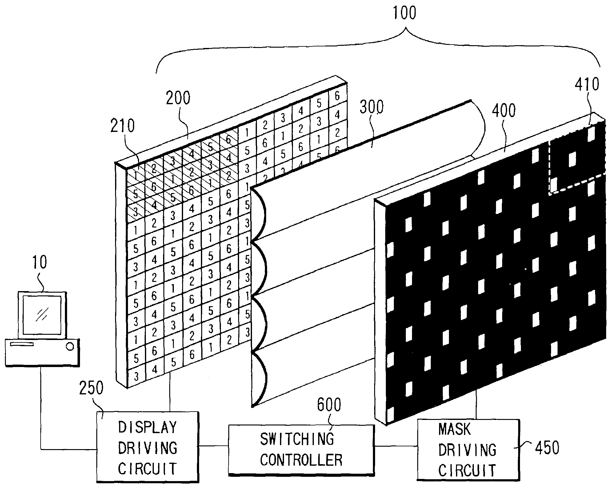
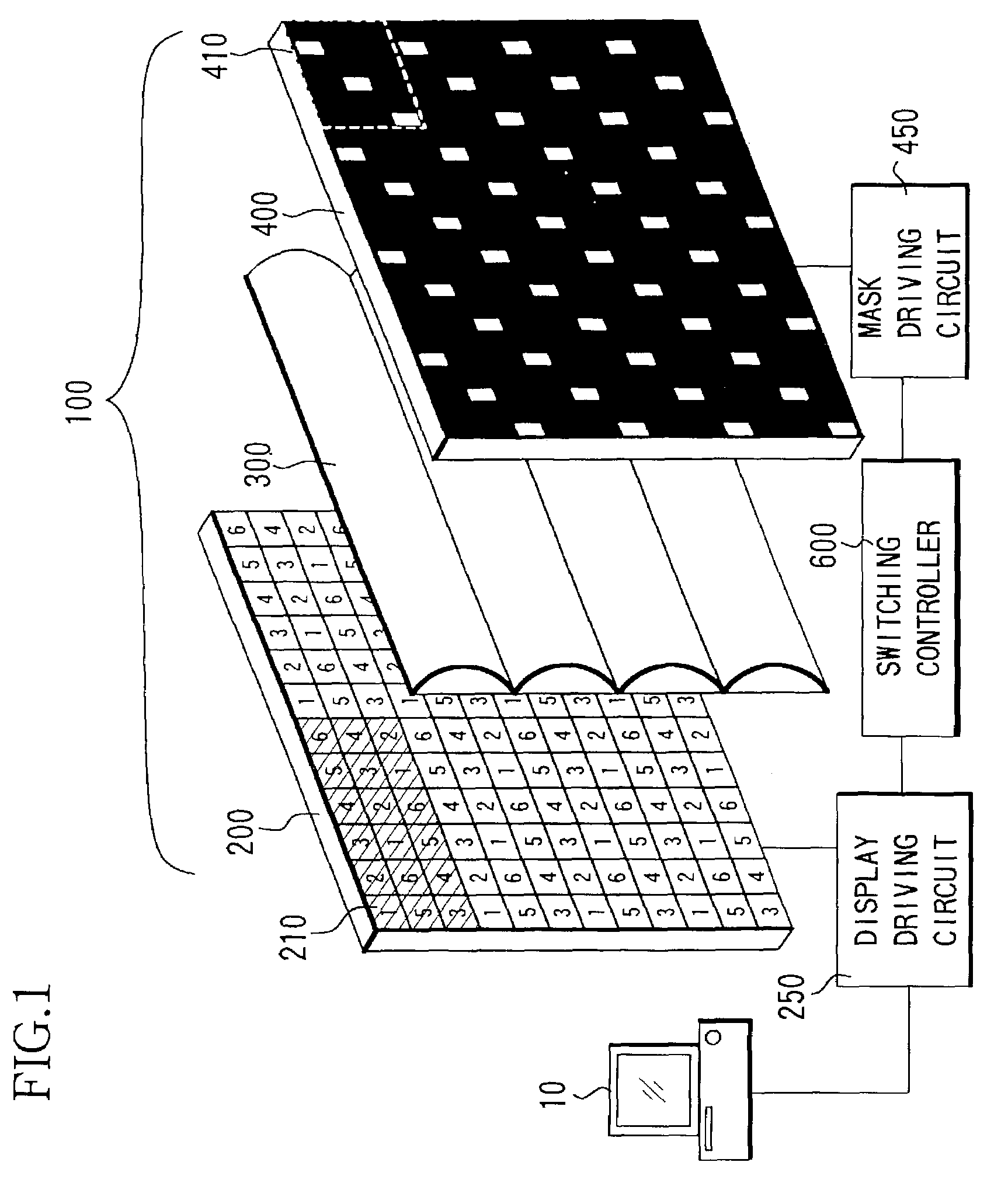
[0180]The stereoscopic image display apparatus 102 comprises a display unit 202, a lenticular lens 300, and a mask 402 as shown in FIG. 25.

(Display Unit 202)

[0181]The display unit 202 comprises a display device where pixels are arranged in the horizontal and vertical directions in a matrix like Embodiment 1, and is driven by a display driving circuit 252.

[0182]The display unit 202 displays combined paral...


PUM


Abstract

A stereoscopic image display apparatus comprising an image display unit that displays combined images formed by combining three different pixels groups in a horizontal direction, which correspond to three different viewpoint images, respectively; a mask member with a plurality of aperture portions that guides light from each pixel group to a corresponding viewpoint; a lenticular lens array arranged between the image display unit and the mask member; and a switching control circuit that switches arrangement of the aperture portions in the mask member in synchronization with switching of the combined images.

Description

BACK GROUND OF THE INVENTION[0001]1. Field of the Invention[0002]The present invention relates to a stereoscopic image display apparatus, and in particular, to a stereoscopic image display apparatus suitable for performing stereoscopic display in a TV set, a VCR, a computer monitor, a game machine, and the like.[0003]2. Description of Related Art[0004]There is a parallax panoramagram as a stereoscopic image display apparatus that expresses conventional motion parallax.[0005]This apparatus has a mask member, in which a plurality of vertical slit-like apertures is arranged horizontally, on a display surface side of a combined parallax image that is combined after a plurality of images corresponding to multiple viewpoints (observation positions) is divided into strip pieces, and shows the plurality of images corresponding to the multiple viewpoints with dividing them into a plurality of viewpoints. Owing to this, it becomes possible to display a natural stereoscopic image that has cont...

Claims


Application Information

Patent Timeline
Patent Type & Authority Patents(United States)
IPC IPC(8): G09G5/00G03B35/24G02B27/22H04N13/00H04N13/04
CPCH04N13/0409H04N13/31
Inventor NISHIHARA, HIROSHITANIGUCHI, NAOSATOSUDO, TOSHIYUKIMORISHIMA, HIDEKI
Owner CANON KK
Why Eureka
Try Eureka