Common-path point-diffraction phase-shifting interferometer

a phase-shifting interferometer and common-path technology, applied in the field of interferometry, can solve the problems of environmental instability, difficult alignment of two-beam interferometers, and increased complexity of interferometer systems, and achieve the effect of introducing phase shifts between coincident objects and reference beams, and reducing the difficulty of adjusting the alignment angl

Inactive Publication Date: 2006-09-12
HEXTECH
View PDF13 Cites 14 Cited by
  • Summary
  • Abstract
  • Description
  • Claims
  • Application Information

AI Technical Summary

Problems solved by technology

Recombining the two beams creates an intensity pattern (interferogram) resulting from constructive and destructive superposition of the beams.
However, such two-beam interferometers are difficult to align and environmentally unstable.
However, generating the phase shift usually adds a level of complexity to the interferometer system.
Introducing phase shifts between coincident object and reference beams, however, has been difficult because of the need to optically distinguish between the two beams traveling along the same path.
One limitation of the device of the '314 patent arises from local distortion of the liquid crystals due to molecular anchoring affects at the surface of microsphere 50.
Another limitation is that dyes must be added to liquid crys

Method used


Image

  • Common-path point-diffraction phase-shifting interferometer
  • Common-path point-diffraction phase-shifting interferometer
  • Common-path point-diffraction phase-shifting interferometer

Examples


Embodiment Construction

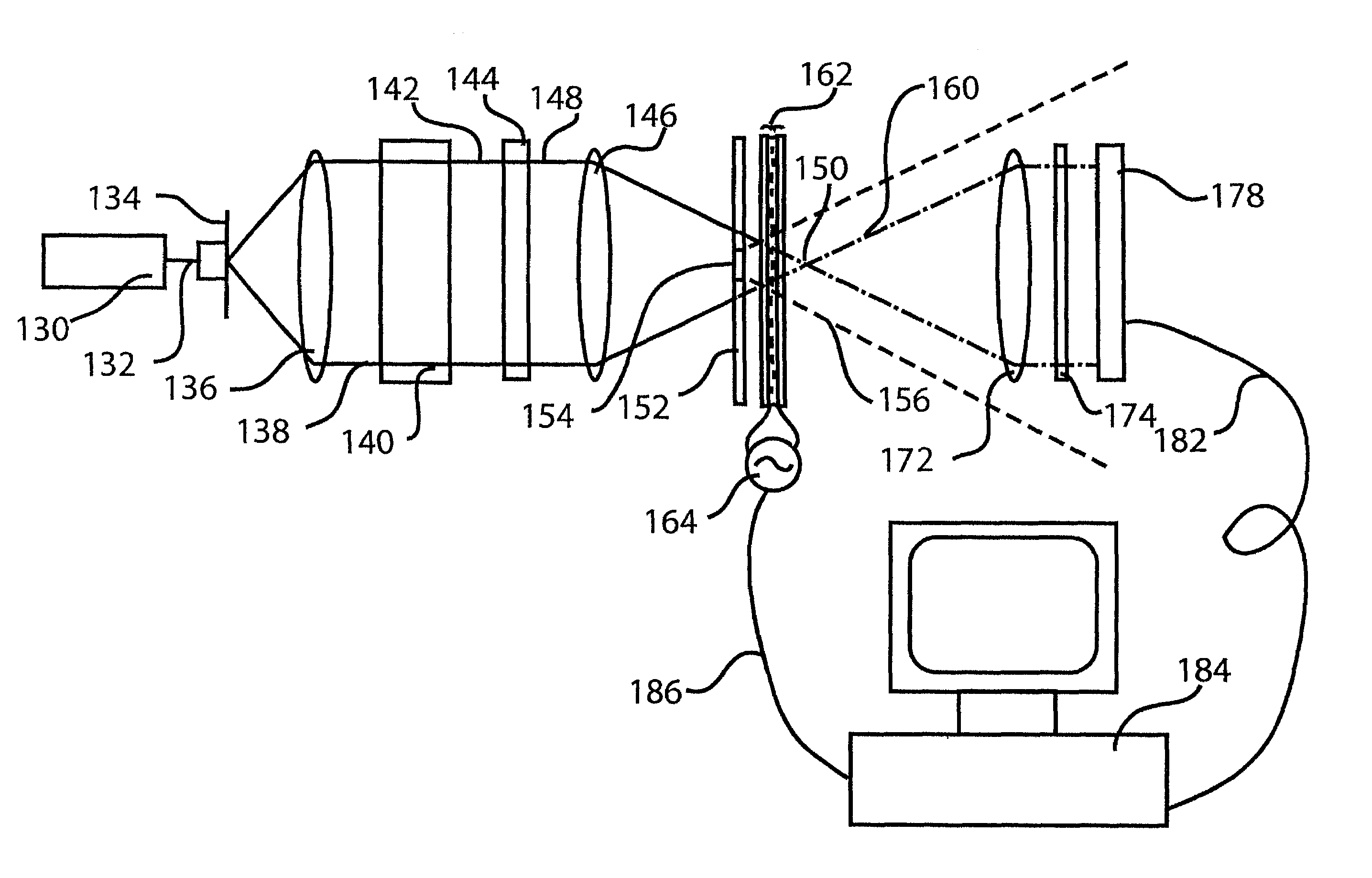
[0031]The present invention provides an improved common-path, phase-shifting interferometer. A diffractive element, such as a pin-hole, is embedded within a polarization element, which may be a birefringent material, to provide two differently polarized beams from an incident beam, one from the diffractive element and the other from the polarization element that surrounds the diffractive element. Nearly perfectly spherical wavefronts emerge from the diffractive element to provide a reference beam for the later analysis. An object beam that carries very much the same information as the incident beam emerges from the polarization element surrounding the diffractive element. However, the polarization element imparts a change in the polarization state to the incident beam traveling there through. In one embodiment of the invention, this change in polarization state is 90° so that the two beams are polarized perpendicularly with respect to each other. However, other angular relationships...


PUM


Abstract

A common-path, point-diffraction, phase-shifting interferometer uses a half wave plate having a diffractive element, such as pin hole. A coherent, polarized light source simultaneously generates a reference beam from the diffractive element and an object beam from remaining portions of the light going through the half wave plate. The reference beam has a nearly spherical wavefront. Each of the two beams possesses a different polarization state. The object and reference beams are then independently phase modulated by a polarization sensitive phase modulator that shifts phase an amount depending on applied voltage and depending on polarization state of the incident light. A polarizer is then used to provide the object and reference beams in the same polarization state with equal intensities so they can interfere to create an interferogram with near unity contrast.

Description

RELATED APPLICATIONS[0001]This application claims the benefit of priority of U.S. Provisional Patent Application No. 60 / 347,160, filed Jan. 9, 2002, entitled “Phase-Shifting Common-Path Interferometer.”FIELD OF THE INVENTION[0002]This invention relates generally to interferometry. More specifically, it relates to a common-path interferometer. Even more specifically, it relates to a common-path, phase-shifting interferometer.BACKGROUND OF THE INVENTION[0003]Interferometers are widely used for characterizing optical elements and systems. Two-beam interferometers split a single coherent optical beam into two beams that travel along separate paths. One beam is used as an object beam that is altered by the test element or system. The other beam is used as a reference beam, which is not transmitted through the system, and retains its original wavefront shape. Recombining the two beams creates an intensity pattern (interferogram) resulting from constructive and destructive superposition of...

Claims


Application Information

Patent Timeline
IPC IPC(8): G01B9/02G01B11/02
CPCG01J9/02G01M11/333G01M11/005G01M11/331G01J2009/0223G01J2009/0261
Inventor COTTRELL, WILLIAM J.
Owner HEXTECH
Why Eureka
Try Eureka