
Bitstream data reduction coding by applying prediction

a bitstream and data reduction technology, applied in the field of data processing apparatus for audio signals, can solve the problems of occupying a considerable amount of bitstream signals, and achieve the effect of increasing lossless compression performan

Inactive Publication Date: 2006-09-12
KONINKLIJKE PHILIPS ELECTRONICS NV
View PDF67 Cites 23 Cited by
  • Summary
  • Abstract
  • Description
  • Claims
  • Application Information

AI Technical Summary

Benefits of technology

[0009]Mainly in audio / speech coding, linear prediction is known to be a powerful technique. By removing redundancy from a speech / audio signal prior to quantization, the entropy of signal after quantization can be significantly reduced. The signals at the input and output of a predictor are either in a floating point or a multi-bit representation.
[0011]In accordance with the invention, prediction is used on bitstream signals, i.e., signals with only two different representation symbols, either ‘0’ or ‘1’. This has the advantage of an increase of lossless compression performance, for only a marginal extra complexity.
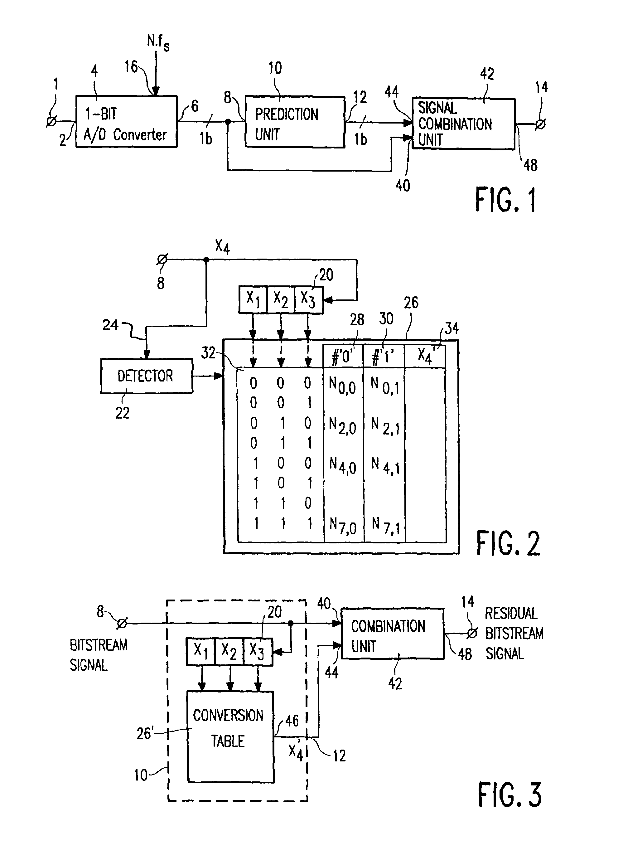
[0012]Experiments have revealed that already a third-order prediction has considerable effect on the statistics of the resulting signal. By means of prediction, as a preprocessing step, prior to data compression, the probability of a ‘1’-bit can be brought down from 50% to about 20%. The effect of this is that the output of the apparatus, in accordance with the invention, contains long runs of ‘zeroes’, which can be exploited by simple Huffman coding or run-length coding.
[0014]Converting an audio signal into a 1-bit bitstream signal has a number of advantages. Bitstream conversion is a high quality encoding method, with the possibility of a high quality decoding or a low quality decoding with the further advantage of a simpler decoding circuit. Reference is made, in this respect, to the publications ‘A digital decimating filter for analog-to-digital conversion of hi-fi audio signals’, by J. J. van der Kam, document D2 in the List of Related Documents, and ‘A higher order topology for interpolative modulators for oversampling A / D converters’, by Kirk C. H. Chao et al, document D3 in the List of Related Documents.

Problems solved by technology

Bitstream signals take up a considerable amount of capacity.

Method used


Image

  • Bitstream data reduction coding by applying prediction
  • Bitstream data reduction coding by applying prediction
  • Bitstream data reduction coding by applying prediction

Examples


Embodiment Construction

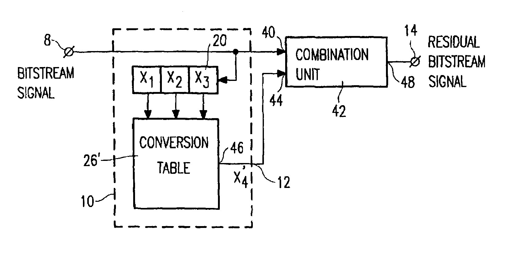
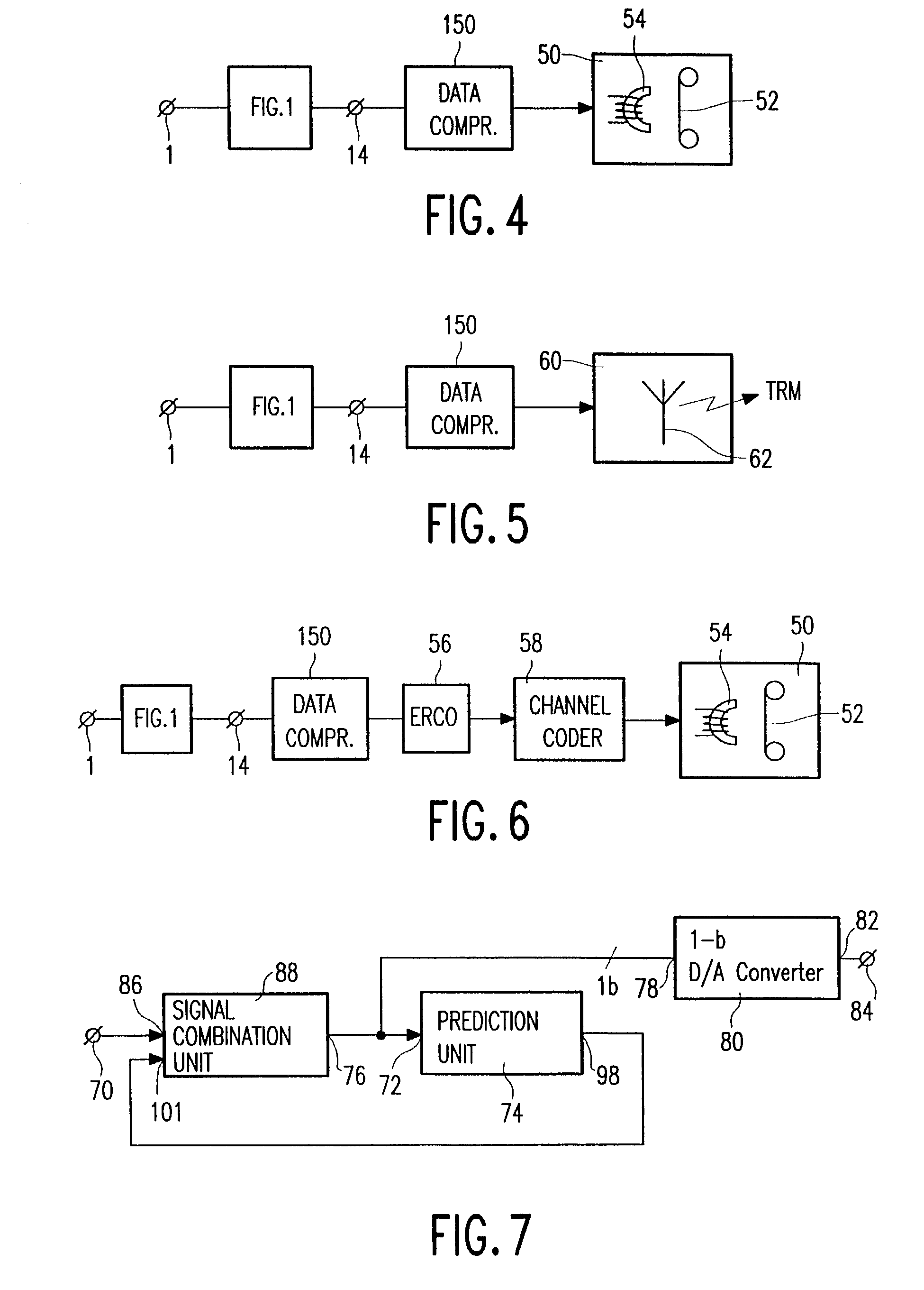
[0040]FIG. 1 shows an embodiment of the data processing apparatus in accordance with the invention, comprising an input terminal 1 for receiving the audio signal. In the present example, the audio signal is an analog audio signal. The input terminal 1 is coupled to an input 2 of a 1-bit A / D converter 4, also called a sigma-delta modulator. An output 6 of the 1-bit A / D converter 4 is coupled to an input 8 of a prediction unit 10, as well as to a first input 40 of a signal combination unit 42. An output 12 of the prediction unit 10 is coupled to a second input 44 of the signal combination unit 42, an output 48 of which is coupled to an output terminal 14.

[0041]The 1-bit A / D converter 4 carries out a 1-bit A / D conversion on the audio signal to form a bitstream signal which is supplied to the output 6. To that end, the A / D converter 4 receives a sampling frequency equal to N·fs via an input 16. fs is a frequency equal to, e.g., 32 kHz, 44.1 kHz or 48 kHz, and N is a large number, such a...


PUM

PropertyMeasurementUnit
frequencyaaaaaaaaaa
frequencyaaaaaaaaaa
frequencyaaaaaaaaaa

Abstract

A data processing apparatus for data processing an audio signal includes an input terminal (1) for receiving the audio signal, a 1-bit A / D converter (4) for A / D converting the audio signal to for a bitstream signal, a prediction unit (10) for carrying out a prediction step on the bitstream signal to form a predicted bitstream signal, a signal combination unit (42) for combining the bitstream signal and the predicted bitstream signal to form a residue bitstream signal, and an output terminal (14) for supplying the residual bitstream signal.

Description

CROSS-REFERENCE TO RELATED APPLICATIONS[0001]This is a continuation of U.S. patent application Ser. No. 09 / 726,764, filed Nov. 30, 2000, now U.S. Pat. No. 6,535,845, which was a continuation of U.S. patent application Ser. No. 08 / 966,375, filed Nov. 7, 1997 now U.S. Pat. No. 6,289,306.BACKGROUND OF THE INVENTION[0002]1. Field of the Invention[0003]The invention relates to a data processing apparatus for data processing an audio signal, to a data processing method, a transmitter comprising the data processing apparatus, a transmitter in the form of a recording apparatus, a record carrier, to second data processing apparatus for reconverting an input signal into a replica of the audio signal, to a receiver comprising the second data processing apparatus, to a receiver in the form of a reproducing apparatus and to a transmission signal comprising a data compressed residual bitstream signal.[0004]2. Description of the Related Art[0005]Data processing an audio signal is well-known in the...

Claims


Application Information

Patent Timeline
Patent Type & Authority Patents(United States)
IPC IPC(8): G10L19/02G11B20/00G11B20/10H03M3/02H03M7/30H03M7/32H05K1/02H05K3/38
CPCG11B20/00007G11B20/10G11B20/10037G11B20/10527H03M7/3002H05K1/0266H05K3/381H05K2203/161H05K2201/09936G11B2020/00065
Inventor VAN DER VLEUTEN, RENATUS J.BRUEKERS, ALPHONS A. M. L.OOMEN, ARNOLDUS W. J.
Owner KONINKLIJKE PHILIPS ELECTRONICS NV
Learn More