Sheet-guiding device for a printing machine

a technology for printing machines and guides, applied in the direction of rotary lithographic machines, pile separation, transportation and packaging, etc., can solve the problems of reducing the effectiveness of sheet guidance, increasing the risk of smearing, and affecting print quality

Inactive Publication Date: 2006-09-19
MANROLANAD AG
View PDF25 Cites 5 Cited by
  • Summary
  • Abstract
  • Description
  • Claims
  • Application Information

AI Technical Summary

Benefits of technology

[0006]It is an object of the invention to provide a sheet-guiding device in a printing machine which permits the uniform guidance of a printing material on a sheet-carrying cylinder, preferably a printing cylinder, in a printing / varnishing unit that is not involved in the printing / varnishing process, and ensures smear-free passage of the sheet printing material through a printing / varnishing nip formed by a blanket / plate cylinder and sheet-carrying cylinder.
[0019]In this case, it is advantageous that, in order to implement the sheet guidance, the blanket / plate cylinder with plate or film and ink / varnish-repellent coating can be rotatably operated. In such case, noticeably low frictional torques occur between the printed and / or varnished printing material transported on a rotating sheet-carrying cylinder, in particular printing cylinder, and an associated, rotating blanket / plate cylinder (with plate or film with ink / varnish-repellent coating) as the relative rotating movements are carried out, by which means the risk of smearing is reduced.
[0020]Moreover, it is advantageous that the splitting of ink / varnish can be reduced considerably by means of the ink / varnish-repellent coating of the plate or film fixed on the blanket / place cylinder so that any impairment to the print quality can additionally be avoided.
[0022]It is likewise advantageous that the sheet-guiding device can be employed irrespective of the modulus of elasticity of the sheet printing materials to be processed.
[0024]In order to provide additional assistance to the sheet guidance, blowing devices can be arranged upstream and downstream of the printing / varnishing nip and assist the transport of the printing materials on the sheet-carrying cylinder.

Problems solved by technology

In the case of these pneumatically operated sheet-guiding devices, a disadvantage is that given the relatively high elasticity of the printing materials, such as for example in the case of board or sheet metal, the effectiveness of the sheet guidance is reduced.
As a result of the relative movement with the blanket / plate cylinder stationary and the printing material being conveyed, the risk of smearing is increased, and as a result the print quality can be impaired.

Method used


Image

  • Sheet-guiding device for a printing machine
  • Sheet-guiding device for a printing machine
  • Sheet-guiding device for a printing machine

Examples


Embodiment Construction

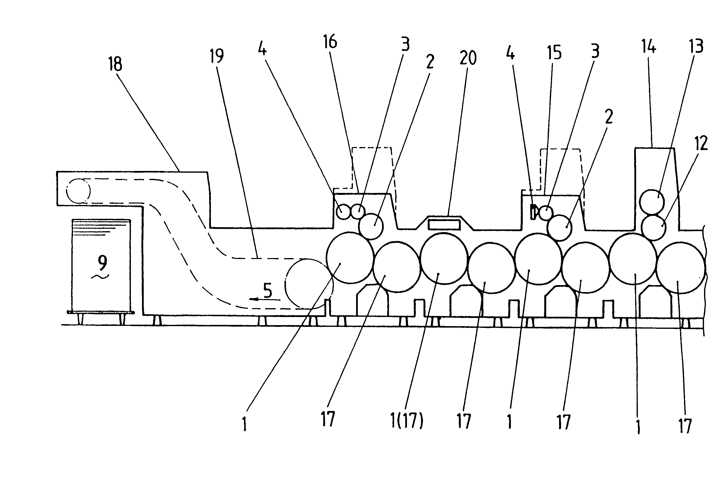
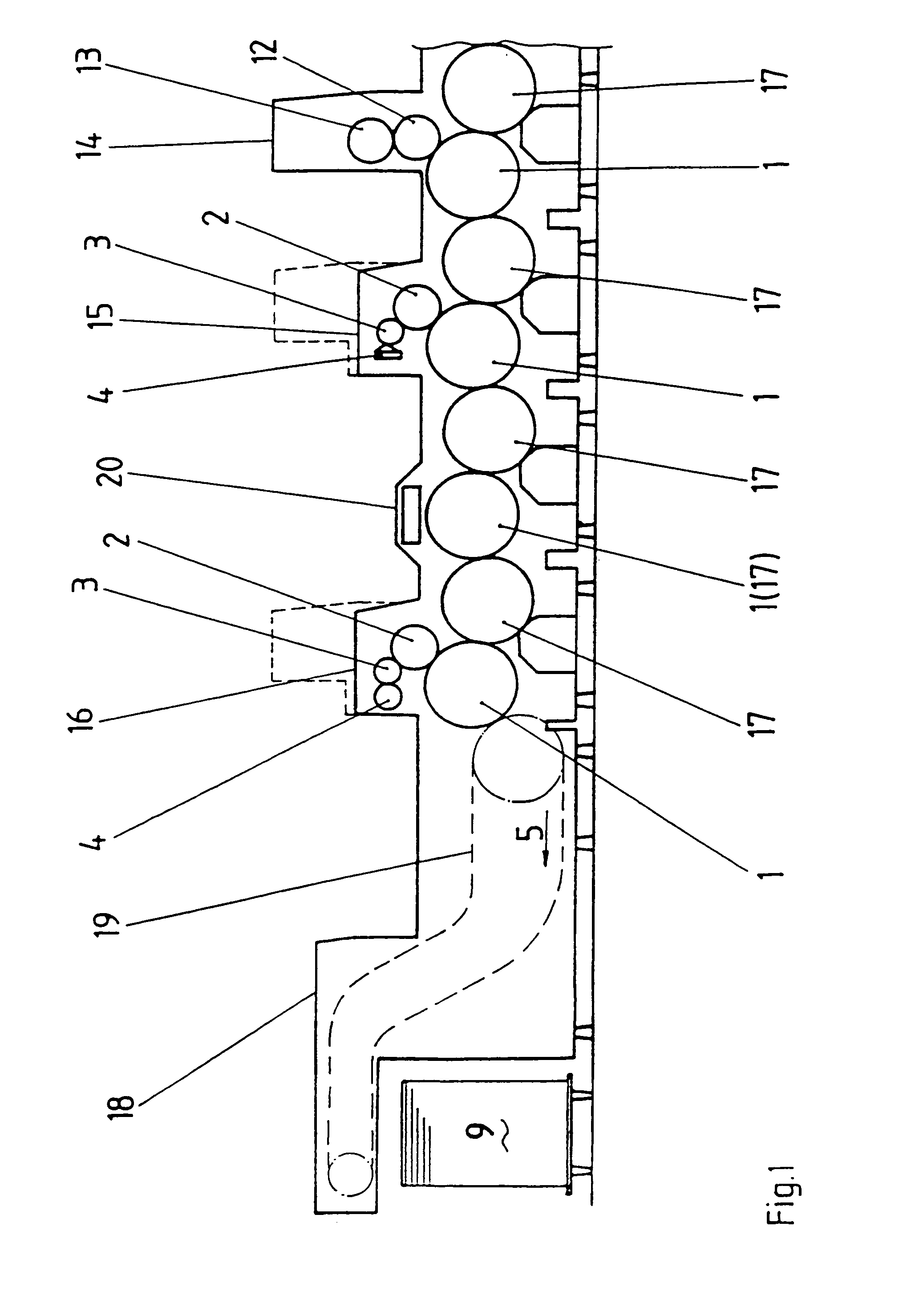
[0027]Referring now more particularly to the drawings, there is shown an illustrative in-line sheet-fed rotary printing machine. In this case, a number of printing units for multi-coloured printing, with sheet-carrying cylinders 1, for example printing cylinders, are lined up with one another and are connected to one another by transfer cylinders 17 or turning systems.

[0028]FIG. 1 shows a partial view of such a printing machine for in-line finishing. Shown here is only a last printing unit 14 having a plate cylinder 13, a blanket cylinder 12 and a printing cylinder 1 as sheet-carrying cylinder. Assigned to the plate cylinder 13 is an inking unit and, if appropriate, a damping unit, which need not be discussed in detail here.

[0029]Arranged downstream of the printing unit 14, in the conveying direction 5, is a first varnishing unit 15, which is formed by a plate cylinder 2, an applicator roll 3 and a metering system 4, for example a metering roll (two-roll unit) or a chamber-type doct...


PUM


Abstract

The invention relates to a sheet-guiding device in a printing machine. The object of the invention is to provide such a sheet-guiding device which in a printing / varnishing unit that is not involved in the printing / varnishing process, permits the smear-free passage of the printing material in a printing / varnishing nip. This is achieved in that on the blanket / plate cylinder 12, 2 there is arranged a printing plate with an ink / varnish-repellent surface coating, it being possible for the blanket / plate cylinder 12, 2 to be driven at the machine speed, and the sheet-carrying cylinder 1 conveying the printed or varnished printing material.

Description

FIELD OF THE INVENTION[0001]The invention relates to a sheet-guiding device for a printing machine and more particularly, to a sheet-guiding device adopted for assisting sheet control in the area of a printing or varnishing nip.BACKGROUND OF THE INVENTION[0002]A conventional sheet-guiding device is disclosed, for example, by EP 0 306 682 A2. The device essentially comprises two blow strips to which blown air is applied and which are arranged upstream and downstream of the press nip formed between a blanket cylinder and a printing cylinder, over the cylinder width and parallel to the axis. The blow strip which is upstream in the conveying direction is arranged in a space above the incoming sheet between the blanket cylinder and printing cylinder. The blown-air stream is directed onto the blanket cylinder, into the printing zone itself and onto the upper side of the sheet carried in the grip of the grippers on the printing cylinder. The downstream blow strip, arranged downstream of th...

Claims


Application Information

Patent Timeline
Patent Type & Authority Patents(United States)
IPC IPC(8): B41F9/00B41F7/02B41F13/00B41F21/00B41F21/04B41F22/00B41F23/00B41F23/08B65H5/12
CPCB41F21/00B41F23/08B41F22/00
Inventor SCHOLZIG, JURGENJUNG, ULRICHKREMER, RUTHWALTHER, THOMAS
Owner MANROLANAD AG
Why Eureka
Try Eureka