Electric ARC welder with background current

a technology of background current and electric arc welding, which is applied in the direction of arc welding apparatus, welding apparatus, manufacturing tools, etc., can solve the problems of not being able to produce imbalances, no separate or supplemental power supply, etc., and achieves the effect of reducing power dissipation by resistors, simple electric arc welding, and effective and low cos

Active Publication Date: 2006-09-19
LINCOLN GLOBAL INC
View PDF4 Cites 6 Cited by
  • Summary
  • Abstract
  • Description
  • Claims
  • Application Information

AI Technical Summary

Benefits of technology

[0004]The present invention involves an improvement that provides a background current using a circuit that is simple, effective and low cost. It does not need a separate power supply. The invention uses the main input transformer, together with background current resistors and diodes to bypass the SCR switches in a full-wave gated bridge power source with two pairs of opposite polarity SCR switches. Consequently, the background welding current is supplied when the appropriate pair of SCR switches are not yet gated to the conductive state for the phase controlled output current. Both the gated full-wave bridge and the low background current are supplied by the secondary winding of the main transformer. This greatly simplifies the electric arc welder, even though it still produces a background current in a unique manner. The background current fills in between the main SCR conduction current pulses. The main transformer secondary provides the background current through a resistor and a diode parallel to each SCR of the bridge. This background current circuit bypasses all of the main SCR switches when operating. Consequently, there is no separate or supplemental power supply. By using the present invention, the main power source provides the background current for either AC welding or DC welding by current following the waveform of the input current to the gated bridge. Since the conduction of the main SCR switches shunts the background resistors, power dissipation by these resistors is reduced when there is increased conduction time of the main SCR switches. Consequently, lost resistor power is minimal during maximum open circuit voltage of the power source. The background current is controlled by a resistance which is determined by resistors each having, in the preferred embodiment, a value in the range of 10–15 ohms. Preferably, each resistor has a value of 12 ohms. The total resistance of the background current resistors is generally 20–30 ohms and preferably about 24 ohms. The level of resistance is divided between resistors at the input and output of the full-wave rectifier used in practicing the present invention. The value of the reactance or individual resistance is selected to provide adequate background current and arc voltage to experience minimal power dissipation. The resistors will be changed for different weld circuits.
[0006]In another aspect of the invention, the background current from the full-wave rectifier is not balanced. To accomplish this feature, the background current resistors are separated so that the AC current during the positive half wave cycle of the main welding secondary is more or less than the AC current during the negative half wave cycle. Consequently, a background current level is different for every half cycle during either AC or DC welding. In this manner, the background current creates cleaning or penetration effect during low current welding. This is beneficial for welding very thin metals, such as aluminum. As is known, during low current operation of an SCR gated bridge it is normally not possible to produce imbalance. By using the present invention and merely selecting the background current resistors that are applicable during the half cycles, imbalance is obtained, even at the low current operation. Thus, the invention not only provides low current operation for a gated bridge power source, but also allows low current imbalance efffects for thin metals, such as aluminum. This is accomplished by selecting the background current resistors to be different for the positive and negative half cycles. This feature can not be done using the two electric arc welders in the patents incorporated by reference herein.
[0008]The primary object of the present invention is the provision of an electric arc welder that provides both DC and AC background current for a welder that does not require a separate supplemental power supply and is therefore more simple and less expensive.

Problems solved by technology

Consequently, there is no separate or supplemental power supply.
As is known, during low current operation of an SCR gated bridge it is normally not possible to produce imbalance.

Method used


Image

  • Electric ARC welder with background current
  • Electric ARC welder with background current
  • Electric ARC welder with background current

Examples


Embodiment Construction

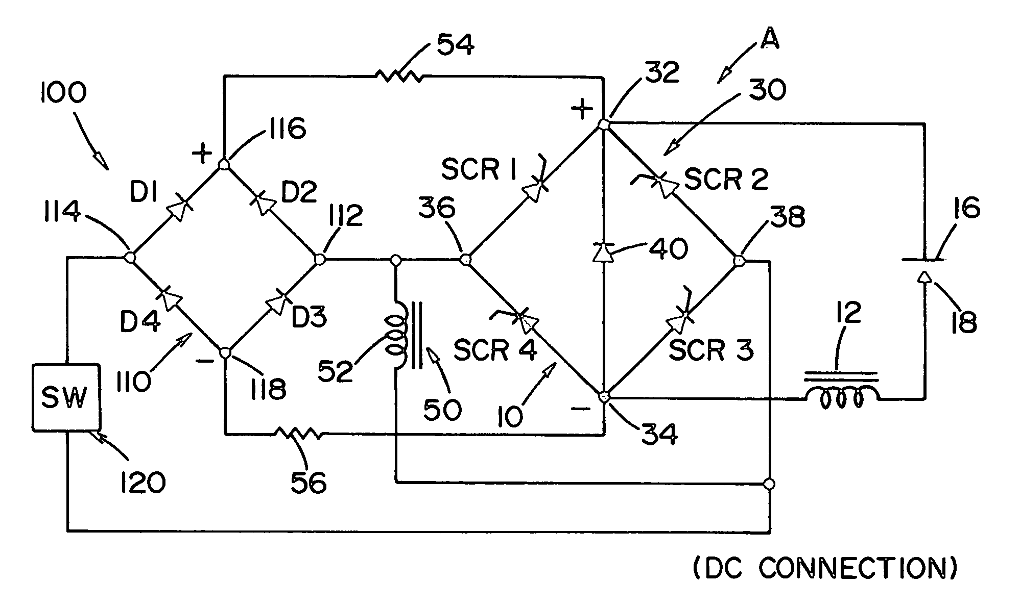
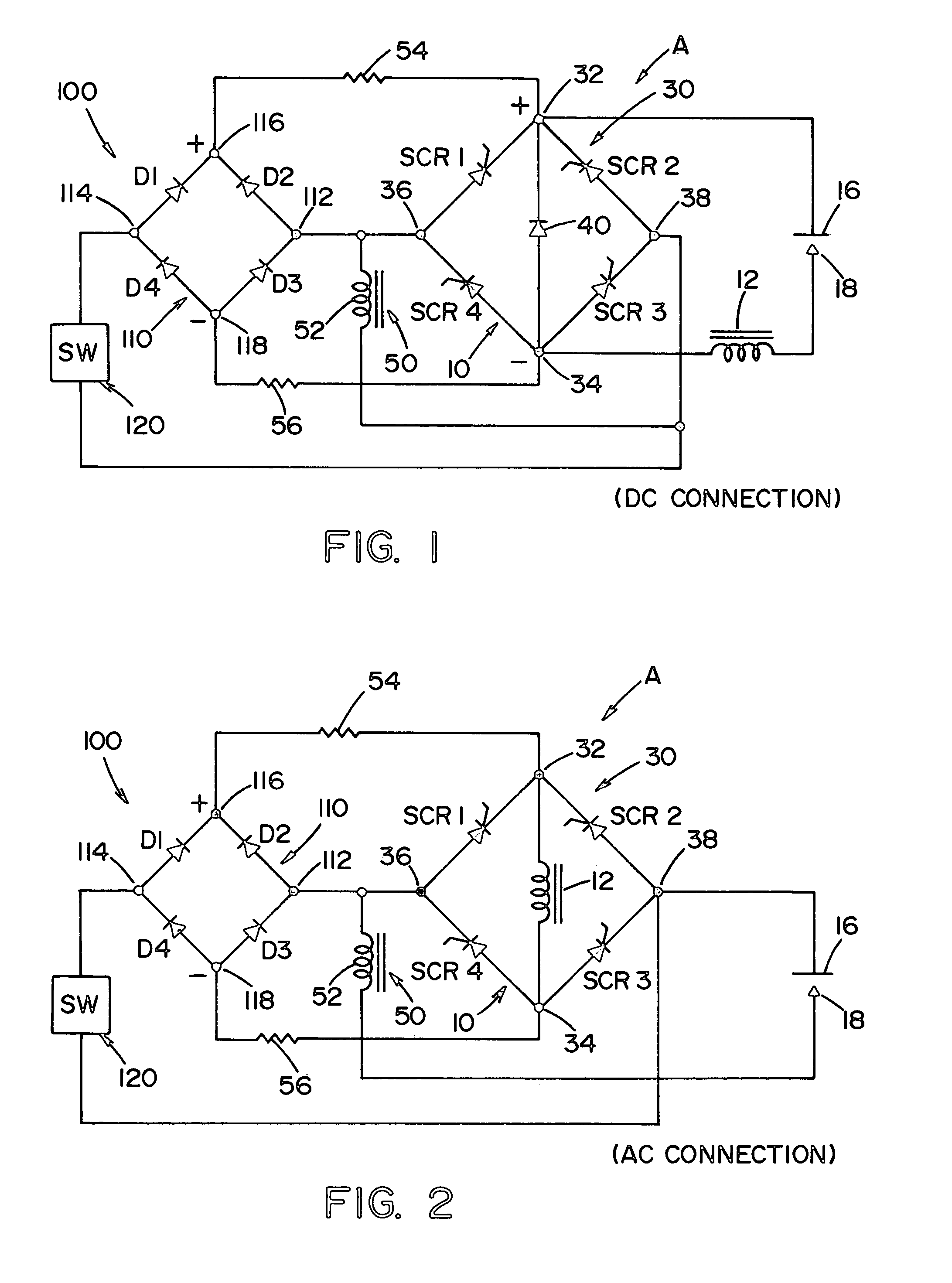
[0024]Referring now to the drawings wherein the showings are for the purpose of illustrating a preferred embodiment of the invention only and not for the purpose of limiting sane, FIGS. 1 and 2 disclose schematically an electric arc welder A constructed in accordance with the present invention for DC welding and AC welding, respectively. The power source of the welder A is a standard gated bridge power source 10 for performing a welding operation across workpiece 16 and electrode 18. Current is directed across workpiece 16 and electrode 18 through a DC choke 12. In accordance with standard welding technology, bridge 30 includes DC output terminals 32, 34 and AC input terminals 36, 38 and is shown connected for a DC welding operation in FIG. 1 with free wheeling diode 40. In FIG. 2 power source 10 is connected for AC operation with DC choke 12 between nodes 32, 34. During positive half cycles, gated switches SCR 1, SCR 3 are conductive. In a like manner, gated switches SCR 2, SCR 4 a...


PUM

PropertyMeasurementUnit
current resistanceaaaaaaaaaa
currentsaaaaaaaaaa

Abstract

An electric arc welder comprising a power source driven by a main input transformer with a secondary winding creating an output pulsating current across the electrode and workpiece of a welding operation is provided with a background current circuit including a full-wave rectifier with AC input and a rectified DC output connected in parallel with the power source across the welding operation wherein the full-wave rectifier is connected in parallel with the secondary winding.

Description

[0001]The present invention relates to an electric arc welder and more particularly to an electric arc welder with a background current circuit for use during low current welding, especially for TIG welding of thin metals.INCORPORATION BY REFERENCE[0002]The present invention is an improvement over the low current power source shown in Samodell U.S. Pat. No. 6,388,232, wherein a supplemental power supply including a full-wave rectifier is used to produce a low current for TIG welding. A low current switch activates the supplemental power supply, which power supply is separately driven by its own input transformer. A similar concept using a supplemental power source is shown in Schwartz U.S. Pat. No. 6,384,373. Each of these patented electric arc welders uses a supplemental power supply for a power source comprising a gated bridge, similar to the power source of the present invention. Consequently, these patents are incorporated by reference herein as background information on the gen...

Claims


Application Information

Patent Timeline
Patent Type & Authority Patents(United States)
IPC IPC(8): B23K9/10B23K9/09
CPCB23K9/1043B23K9/091
Inventor SAMODELL, RALPH M.
Owner LINCOLN GLOBAL INC
Why Eureka
Try Eureka