Vehicle surroundings monitoring device, and image production method/program

a monitoring device and vehicle environment technology, applied in the field of vehicle surroundings monitoring devices and image production methods/programs, can solve the problems of unnatural synthesized images, possible wrong display of obstacles, and the use of conventional techniques described abov

Inactive Publication Date: 2006-09-19
PANASONIC CORP
View PDF22 Cites 154 Cited by
  • Summary
  • Abstract
  • Description
  • Claims
  • Application Information

AI Technical Summary

Benefits of technology

[0009]An object of the present invention is providing a technology that enables presentation of an image showi...

Problems solved by technology

However, the conventional techniques described above have the following problems.
Therefore, the shape of the obstacle is distorted in a synthesized image, and this makes the synthesized image unnatural.
However, if the computed position includes errors greatly, the obstacle may possibly be displayed at a wrong position, or the obstacle may not be displayed in a synthesized image.
For example, in the ...

Method used


Image

  • Vehicle surroundings monitoring device, and image production method/program
  • Vehicle surroundings monitoring device, and image production method/program
  • Vehicle surroundings monitoring device, and image production method/program

Examples


embodiment 1

(Embodiment 1)

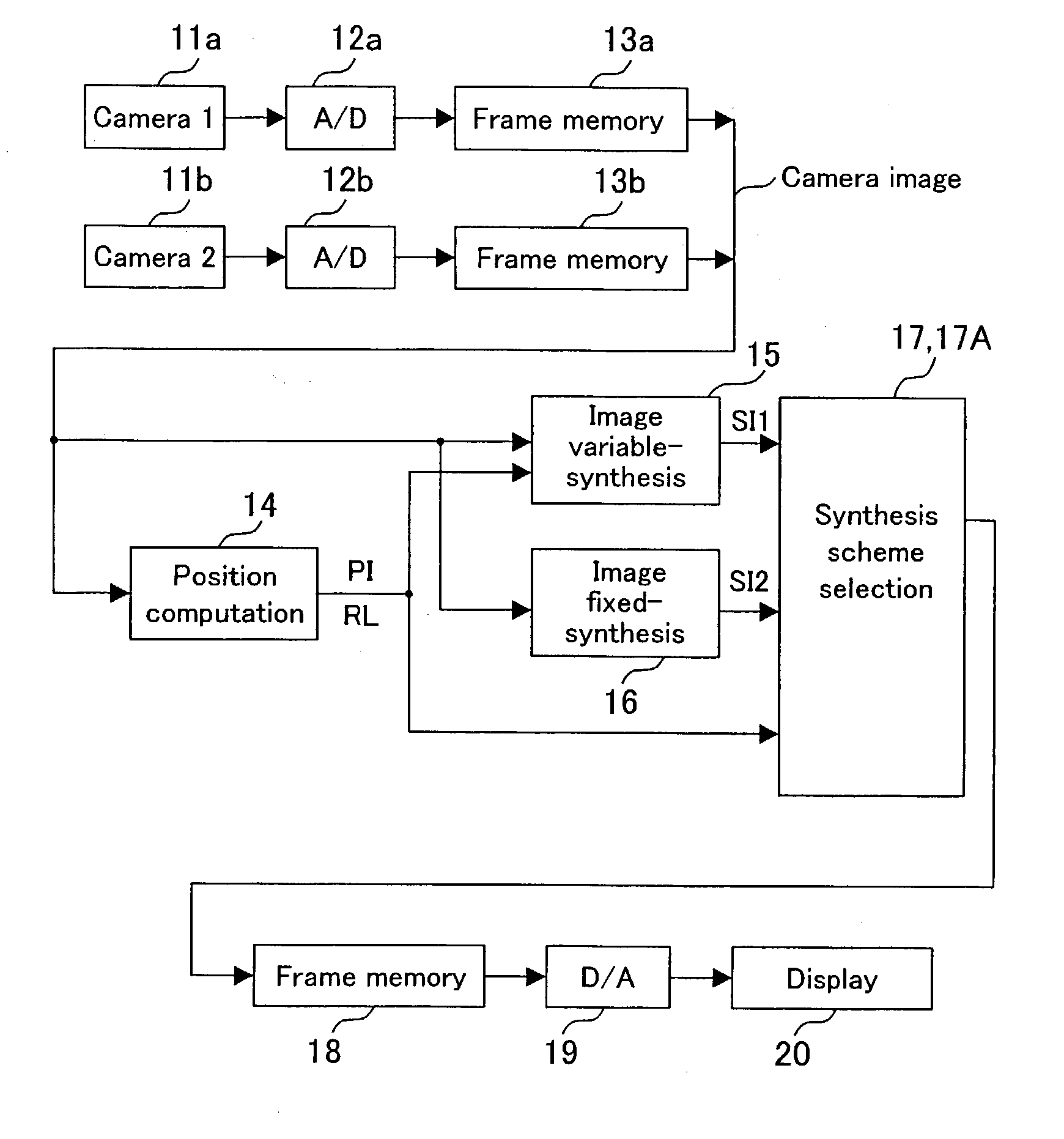
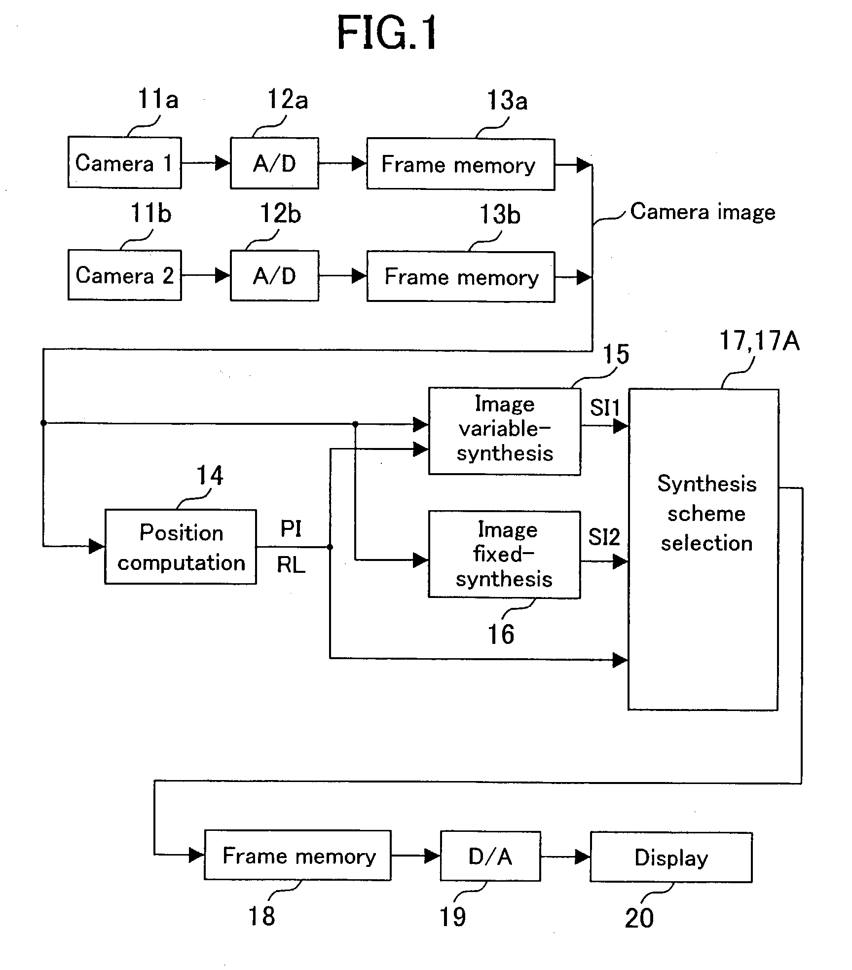
[0039]FIG. 1 is a block diagram of a vehicle surroundings monitoring device of Embodiment 1 of the present invention. The vehicle surroundings monitoring device of FIG. 1 produces a synthesized image showing the situation around a vehicle from images taken with cameras capturing the surroundings of the vehicle, and presents the synthesized image to a display.

[0040]Referring to FIG. 1, the vehicle surroundings monitoring device includes: cameras 11a and 11b for capturing the surroundings of a vehicle; A / D converters 12a and 12b for digitizing an analog video signal obtained from the cameras 11a and 11b; and frame memories 13a and 13b for temporarily holding the digitized camera images. The device also includes: a position computation section 14 for computing position information PI and the reliability RL of the position information PI, for a plurality of points in camera images; an image variable-synthesis section 15 for transforming the camera images using the position...

embodiment 2

(Embodiment 2)

[0079]A vehicle surroundings monitoring device of Embodiment 2 has the same configuration as that of Embodiment 1 shown in FIG. 1, except that a synthesis scheme selection section 17A in this embodiment superimposes on a synthesized image an indication according to a feature of the synthesized image. In addition, in this embodiment, the position information PI itself is used in combination with the reliability RL of the position information for the selection of a synthesized image.

[0080]Specifically, the synthesis scheme selection section 17A operates as follows. The synthesis scheme selection section 17A extracts points belonging to an obstacle that is likely to appear in a synthesized image from n corresponding points specified by the position computation section 14. In other words, the synthesis scheme selection section 17A extracts points that are apart from the road surface by a predetermined distance and belong to a region used for image synthesis, based on three...

embodiment 3

(Embodiment 3)

[0085]FIG. 9 is a block diagram of a vehicle surroundings monitoring device of Embodiment 3 of the present invention. The same components as those in FIG. 1 are denoted by the same reference numerals, and the description thereof is omitted here. The configuration of FIG. 9 is different from that of FIG. 1 in that the vehicle is provided with an obstacle sensor 31 for detecting an obstacle around the vehicle and outputting distance information DI, and that a synthesis scheme selection section 17B selects a synthesized image by additional use of the distance information DI sent from the obstacle sensor 31. The obstacle sensor 31 measures the distance from a neighboring obstacle at a fixed period, and outputs distance information DI if an obstacle exists within the range of a predetermined distance. Assume herein that the obstacle sensor 31 is an ultrasonic sensor in which the distance from an object is computed from the time required for ultrasound emitted to return afte...


PUM


Abstract

A synthesized image showing the situation around a vehicle is produced from images taken with cameras capturing the surroundings of the vehicle and presented to a display. A position computation section computes position information and the reliability of the position information, for a plurality of points in the camera images. An image variable-synthesis section produces a first synthesized image from the camera images using the position information. An image fixed-synthesis section produces a second synthesized image by road surface projection, for example, without use of the position information. A synthesis scheme selection section selects either one of the first and second synthesized images according to the reliability as the synthesized image to be presented.

Description

BACKGROUND OF THE INVENTION[0001]The present invention relates to a technology on a vehicle surroundings monitoring device in which images taken with a camera capturing the surroundings of a vehicle are transformed to provide a synthesized image showing the situation around the vehicle.[0002]In recent years, to help drivers drive safely, vehicle surroundings monitoring devices for monitoring the surroundings of a vehicle with a camera have been increasingly put into practical use.[0003]In one type of conventional vehicle surroundings monitoring device, a camera is placed so as to capture a blind spot for the driver, such as an area behind the vehicle. Image taken with the camera are transformed by a predetermined fixed method, to be displayed on a display. For example, in a technique disclosed in Japanese Laid-Open Patent Publication No. 03-99952 (literature 1), a plurality of cameras are placed on a car as shown in FIG. 20A. Images of the surroundings of the car taken with the came...

Claims


Application Information

Patent Timeline
IPC IPC(8): H04N7/18H04N9/47G01S5/16G01S11/12G06T7/00
CPCG01S11/12H04N7/181G06T7/0044G06T7/0022G01S5/16G06T7/74G06T7/97
Inventor NOBORI, KUNIONAKAGAWA, MASAMICHISATO, SATOSHINAKATA, MIKIYA
Owner PANASONIC CORP
Why Eureka
Try Eureka