
Control system and method for on-line editing of user program

a control system and user program technology, applied in the direction of program control, electrical programme control, memory address/allocation/relocation, etc., can solve problems such as difficult to correct at once ladder circuits scattered at a plurality of different positions within the user program, and may be discovered in the program

Active Publication Date: 2006-09-19
ORMON CORP
View PDF18 Cites 25 Cited by
  • Summary
  • Abstract
  • Description
  • Claims
  • Application Information

AI Technical Summary

Benefits of technology

[0019]The invention further relates to a method of editing a user program of a programmable controller by using a programming tool. The programmable controller for this method is presumed to be connected to a CPU unit having two memories for storing a user program and adapted to carry out cyclic operations of I / O refresh, user program execution and peripheral service processes, and the method of this invention may be characterized as comprising the steps of preliminarily storing the user program in these two memories with same contents, selecting the user program stored in a selected one of these two memories (the “selected memory”) as the object of execution before the user program is edited with the programming tool and continuing the cyclic operations by the CPU unit, uploading a user program stored in either of the two memories (either the selected memory or the other memory) with the programming tool while the CPU unit is in operation, and editing the uploaded user program with the programming tool, downloading the edited user program, after the step of editing is completed and while the CPU unit is in operation, to the other of the two memories (the “other memory”) and storing the downloaded user program with the programming tool, causing the CPU unit, after the step of downloading is completed, to switch the object of execution from the user program in the selected memory to the user program in the other memory and to execute the edited user program wherein the CPU unit is arranged to execute the edited user program, and causing the CPU unit to store the edited user program of the other memory to the selected memory, thereby causing the two memories to store user programs with same content.

Problems solved by technology

There are situations where something wrong may be discovered in a program or something wrong may happen in the operation even after a user program is executed (in the calculation process of the aforementioned cyclic operations) by the CPU unit of a PLC and the production equipment or the like has actually started to operate.
With such a prior art method of on-line editing, it is relatively easy to edit one circuit by one process but it is difficult to correct at once ladder circuits scattered at a plurality of different positions within a user program because it is extremely cumbersome to add a jump command temporarily to each of the plurality of portions of the user program to be edited.
Moreover, such jump commands that have been temporarily added must be removed after the editing is completed and this makes the work even more cumbersome.
If even one of these temporarily added commands fails to be removed, the edited program will not operate normally.
Conventional on-line editing methods, furthermore, could not work on function blocks.
Thus, if a conventional method of editing an ordinary circuit is applied to a function block, many jump commands will have to be inserted and both the work of inserting these jump commands and that of removing these inserted jump commands after the editing are extremely cumbersome.
Thus, the work of inserting and removing jump commands becomes extremely cumbersome, as in the case of editing a plurality of parts of the ladder circuit of a main user program, as described above.
Another problem with the on-line editing is that the portion of the user program being edited is not processed because it is skipped by a jump instruction, and hence if a portion of the program which is indispensable to the control is edited, there is likely to be an adverse effect on the operations of the PLC and accordingly also the operations of the production equipment or the like.
In other words, the on-line editing cannot be carried out freely and indiscriminately on any portion of a program.

Method used


Image

  • Control system and method for on-line editing of user program
  • Control system and method for on-line editing of user program
  • Control system and method for on-line editing of user program

Examples


Embodiment Construction

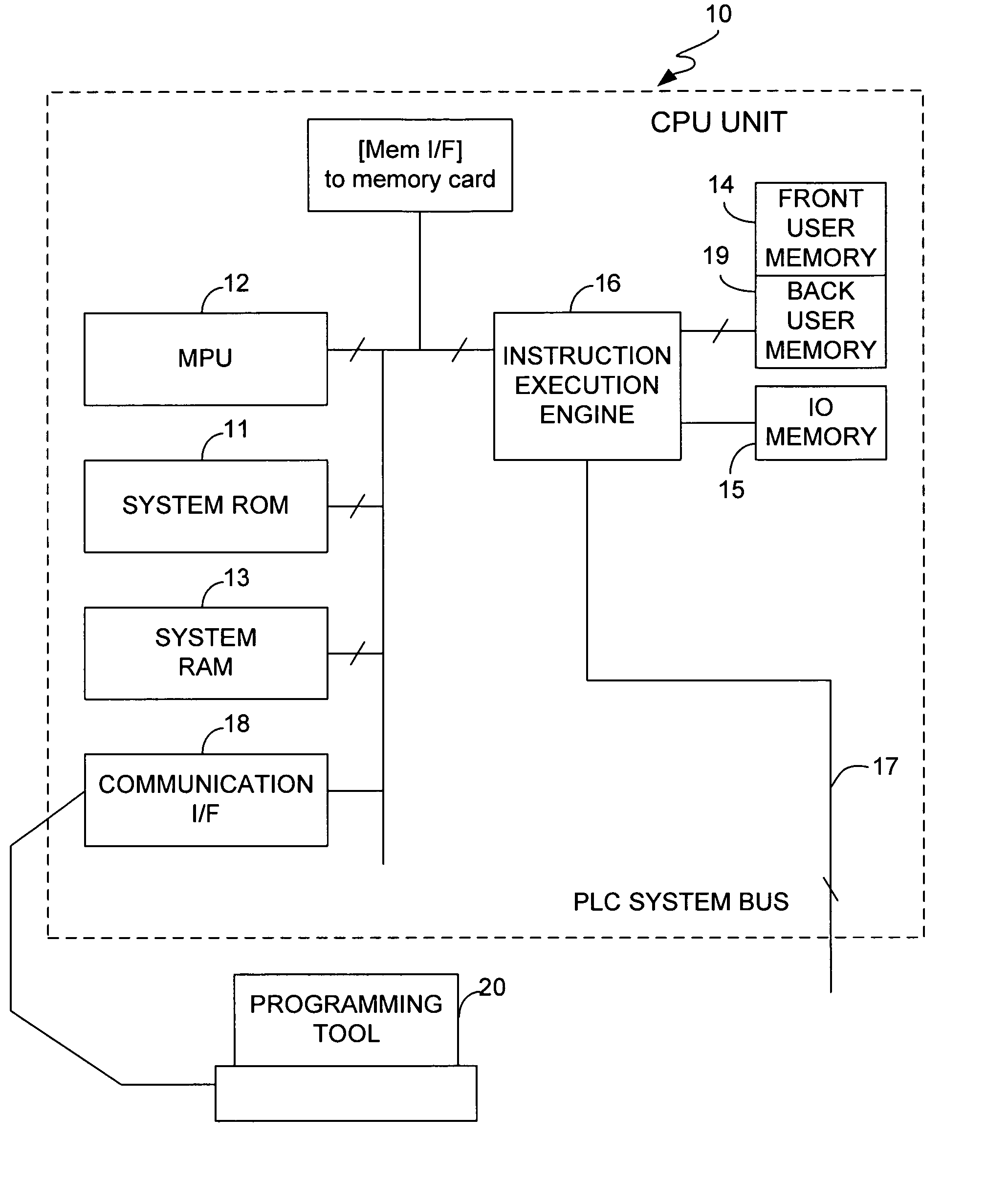
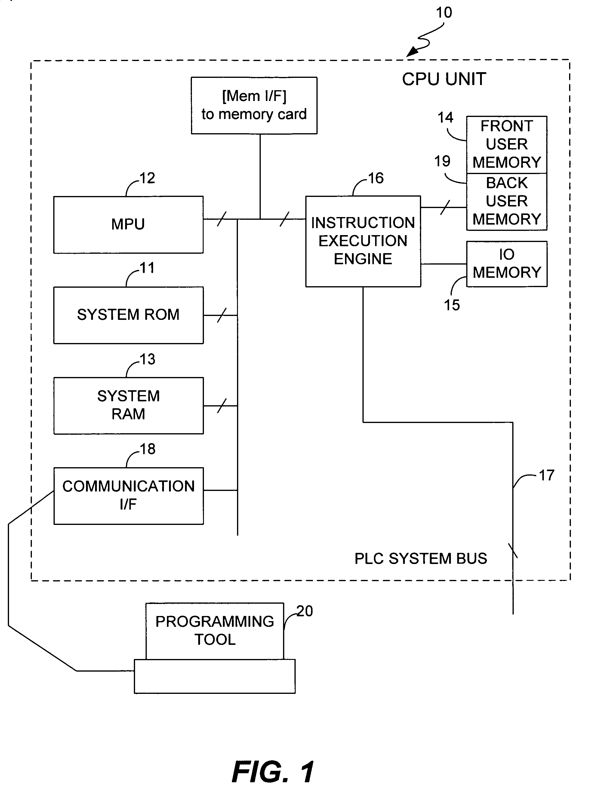
[0032]The invention is described next by way of an example. FIG. 1 shows a CPU unit 10 embodying this invention, serving as one of the constituent units of a PLC. The system program for carrying out the cyclic operations of the CPU unit 10 is stored in a ROM (the “system ROM”) 11. It is an MPU 12 that carries out specified operations according to the system program in the system ROM 11 while appropriately making use of a system RAM 13 serving as a work memory. A user program which has preliminarily been created by the user by using a programming tool is stored in a user memory 14. I / O data and parameters to be used in the logical calculation when the user program is executed are stored in an IO memory 15. During the IN-refresh process prior to the execution of the user program, the CPU unit 10 takes in IN data from an I / O unit (not shown) connected through a PLC system bus 17. The CPU unit 10 carries out its calculation process on the basis of these IN data and outputs the results o...


PUM


Abstract

A control system includes a programmable controller having a CPU unit that carries out cyclic operations of processes. An additional temporary user memory is provided in addition to a regular user memory. When an on-line editing of a user program is to be carried out, the program is stored in both memories and the program stored in the temporary memory is called by an instruction execution engine to be executed. After the on-line editing is completed on the user program stored in the user memory, the program execution is based on the edited user program stored in the user memory.

Description

BACKGROUND OF THE INVENTION[0001]This invention relates to a control system and on-line editing of user program on a programmable controller.[0002]Programmable controllers (PLC) are commonly being used as a control device in factory automation. A PLC is usually comprised of a plurality of units of various kinds combined appropriately together. Examples of such constituent units include a power source unit serving as a power source, a CPU unit for controlling the PLC as a whole, an input unit for inputting signals from switches and sensors that are installed at appropriate positions on a production machine or the like of the factory automation, an output unit for transmitting control outputs to actuators or the like and a communication unit for carrying out processing to a communication network such as carrying out data communications with a programming tool, a monitoring host apparatus and other PLCs.[0003]The control operations by a CPU unit of a PLC starts with an initialization p...

Claims


Application Information

Patent Timeline
IPC IPC(8): G05B19/42G06F12/00G06F12/12G06F12/16G06F13/00G05B11/01G05B9/02G05B19/05
CPCG05B19/056G05B2219/13153
Inventor OKA, MINORUDEKI, JINTAROYAOITA, KOJIICHIMURA, KATSUHIKOONO, AKIO
Owner ORMON CORP
Learn More