Printing machine

a printing machine and frame technology, applied in printing presses, rotary presses, printing, etc., can solve problems such as intermittent printing, and achieve the effects of optimum printing quality, simple manner, and dimensional stability of machine frames

Inactive Publication Date: 2006-09-26
FISCHER & KRECKE
View PDF9 Cites 5 Cited by
  • Summary
  • Abstract
  • Description
  • Claims
  • Application Information

AI Technical Summary

Benefits of technology

[0005]It is an object of the invention to provide a printing machine of the type described above, wherein the d

Problems solved by technology

From the European patent specification EP 0 150 047 of the applicant the problem is known that, within a short period of time after starting the print

Method used


Image

  • Printing machine
  • Printing machine
  • Printing machine

Examples


Embodiment Construction

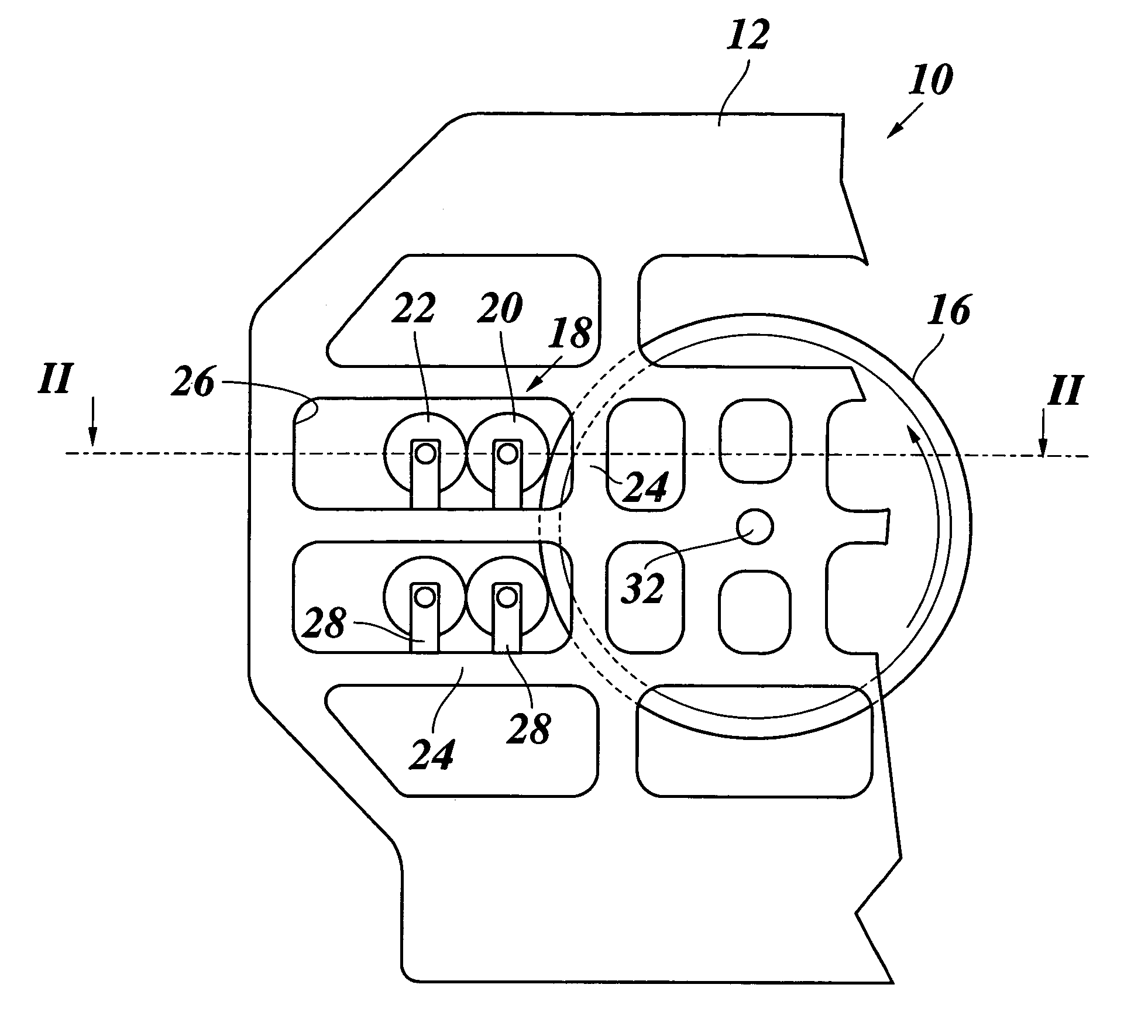
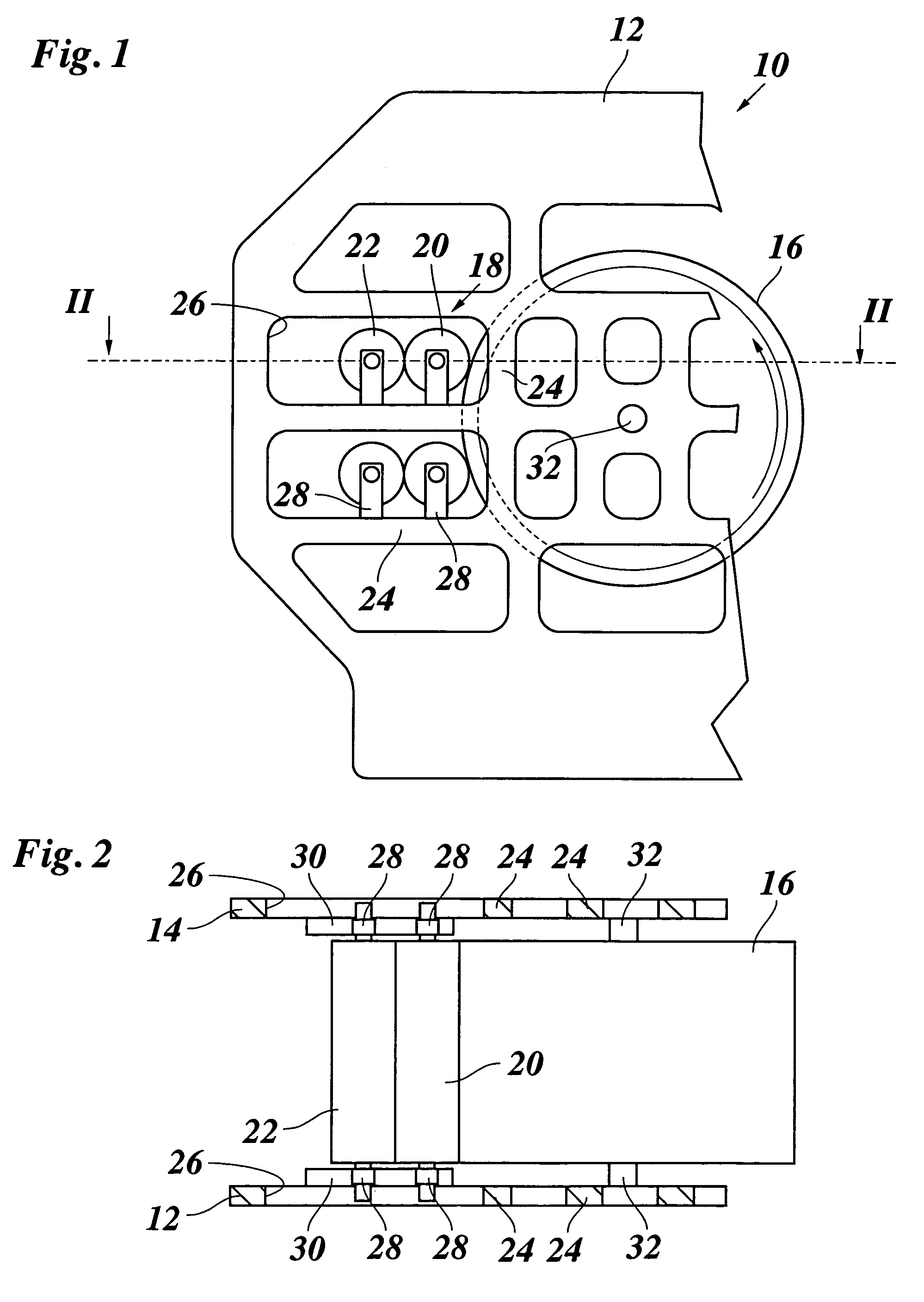
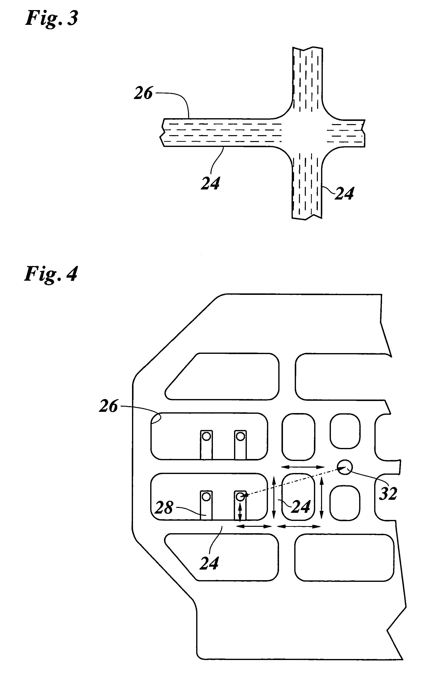
[0021]FIG. 1 shows a partial side view of a flexographic printing machine. FIG. 2 shows a sectional view along the line II—II of FIG. 1. The printing machine comprises a framing in the form of frame 10, which comprises two side members 12 and 14. In FIG. 1, only the side member 12 is visible. An impression cylinder 16 is mounted between the side members 12 and 14, and several inking units 18 are arranged around the periphery of the impression cylinder 16. Each inking unit 18 comprises a printing cylinder 20 and an inking roller 22. The side members 12 and 14 each comprise struts 24, inbetween which several windows 26 are formed. The printing cylinders 20 and the inking rollers 22 are mounted on slides 28 which are mobile along guiding rails 30. The guiding rails 30 each are mounted below a corresponding window 26 at the inner side of the side members 12 and 14, respectively. The impression cylinder 16 comprises axle journals 32 with which it is journalled in the side members 12 and ...


PUM


Abstract

Printing machine with a machine frame (10) and at least two cylinders (16, 20) which cooperate during printing, and which are mounted in a framing (12, 14; 24) formed by the machine frame (10). The framing (12, 14; 24) includes a material which has, at least in a direction transverse to the axes of rotation on the cylinders (16, 20), a linear thermal expansion coefficient that is less than 2×10⁻⁶ K−1. The material can be a composite material, particularly a carbon fiber reinforced plastic.

Description

BACKGROUND OF THE INVENTION[0001]The invention relates to a printing machine with a machine frame and at least two cylinders that cooperate during printing and that are mounted in a framing formed by the machine frame.[0002]In printing machines, the cylinders which cooperate during printing usually are mounted at each of both ends of each cylinder in a side member of the machine frame. In a flexographic printing machine, for example, several printing units with printing cylinders are arranged around an impression cylinder. To achieve high quality printing results it is necessary that an optimal distance between the impression cylinder and the individual printing cylinders of the printing units is precisely adjusted. An expansion or a contraction of the impression cylinder caused by temperature variations would notably impair the printed image due to the large diameter of the impression cylinder, which can be in the range from 2 m to 3.5 m, for example. For this reason, the impressio...

Claims


Application Information

Patent Timeline
IPC IPC(8): B41F5/00B41F13/00
CPCB41F13/0024
Inventor KOLBE, WILFRIEDSTEINMEIER, BODOKUCKELMANN, ANDREAS
Owner FISCHER & KRECKE
Why Eureka
Try Eureka