Connecting rod for an internal combustion engine

a technology of connecting rods and internal combustion engines, applied in the direction of shafts and bearings, instruments, mechanical control devices, etc., can solve the problems of tensile load, connecting rods may underlie even higher or predominantly tensile loads, etc., and achieve the effect of reducing weigh

Inactive Publication Date: 2006-09-26
FEV MOTORENTECHN GMBH
View PDF8 Cites 24 Cited by
  • Summary
  • Abstract
  • Description
  • Claims
  • Application Information

AI Technical Summary

Benefits of technology

[0006]It is an object of the invention to provide a connecting rod...

Problems solved by technology

However, in the case of very high rotational speeds significant tensile loads may appear as a result from inertia forces...

Method used


Image

  • Connecting rod for an internal combustion engine
  • Connecting rod for an internal combustion engine
  • Connecting rod for an internal combustion engine

Examples


Embodiment Construction

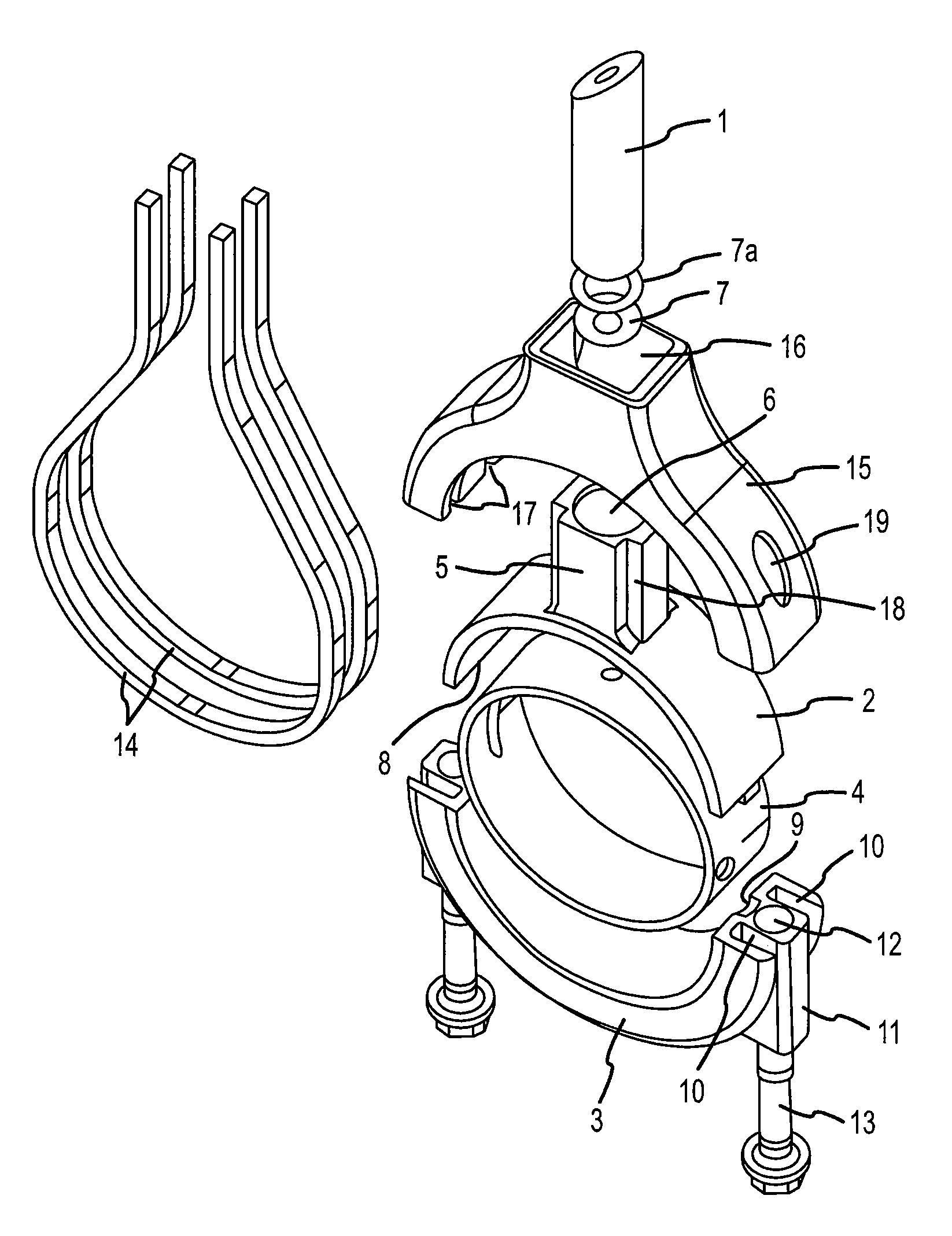
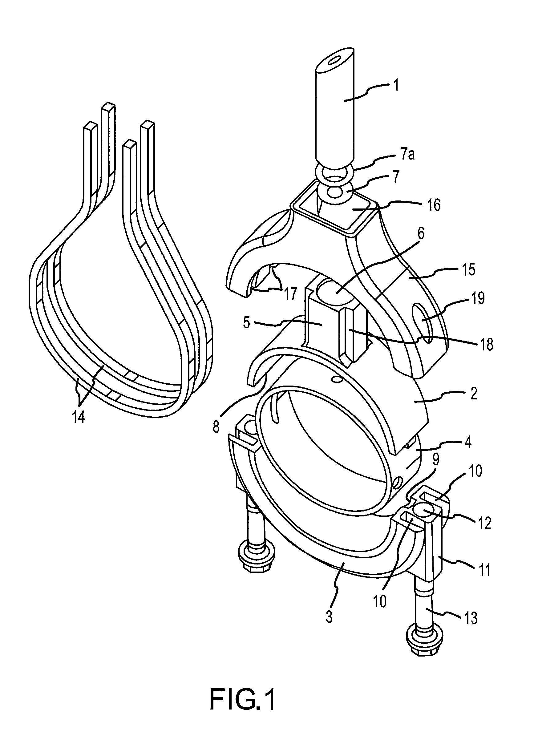
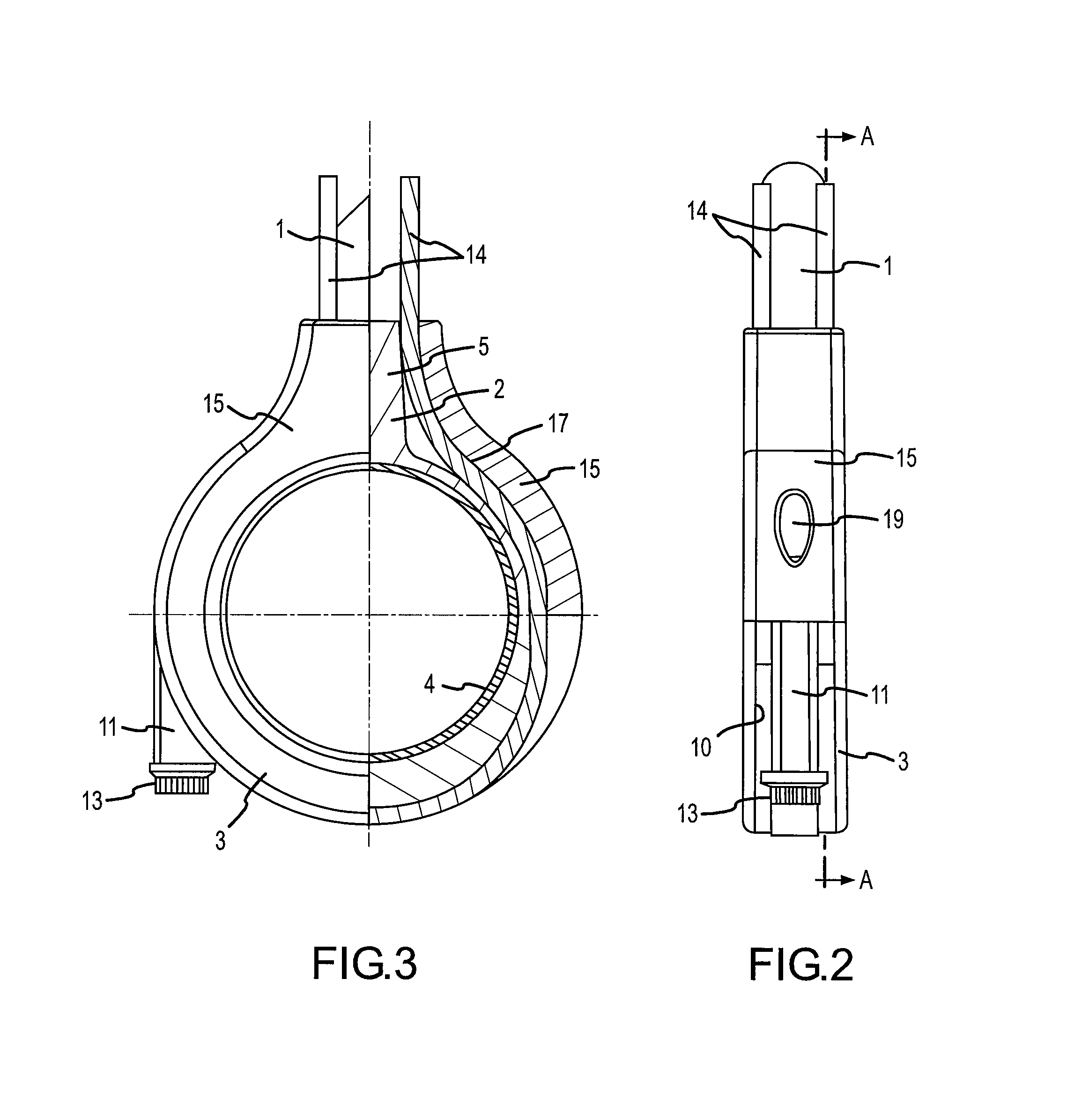
[0023]The embodiment of the connecting rod shown in the drawings comprises a center rod 1 in the form of a rod or a hollow rod, i.e. a tube of circular or non-circular cross section. The center rod 1 may be of conventional material such as, but not limited to, steel, aluminium, and titanium. However, a light weight material in the form of a fiber-reinforced composite material is preferred.

[0024]The connecting rod further comprises a first cap 2 and a second cap 3. The caps 2 and 3 are substantially semicircular to take up a bearing 4, according to this embodiment two bearing shell halves of a big-end bearing. The first cap 2 is provided with a hollow pilot 5 having a central opening or bore 6 taking up the center rod 1. Spring elements 7 and / or shims 7a may be inserted into bore 6 before the insertion of the center rod 1. The pilot 5 preferably has a cross section with a polygonal outer contour.

[0025]The first and second caps 2, 3 and the bearing 4 form a big eye at the correspondin...


PUM


Abstract

The invention relates to a connecting rod for an internal combustion engine, comprising a center rod having a first and a second end, the first end being provided with a big eye and the second end being provided with a connecting piece; wherein the big eye comprises a first and a second cap for taking up a bearing in between, the first cap being arranged on the center rod; at least one endless fiber loop wrapped around the whole connecting rod; and a tensioner arranged over the first cap, the at least one fiber loop being placed between the tensioner and the first cap, the tensioner being connected to the second cap by the fastening elements under assembling together the first and second caps and tensioning the at least one fiber loop.

Description

FIELD OF THE INVENTION[0001]The present invention concerns a connecting rod for an internal combustion engine as it is used generally for connecting a crankshaft of an internal combustion engine with a piston.BACKGROUND OF THE INVENTION[0002]Normally, connecting rods for connecting a crankshaft of an internal combustion engine with a piston are generally subjected to compressive loads so that the connecting rods should have a sufficient stability against buckling. This especially applies for modern Diesel engines with high cylinder pressures and at the same time comparatively low engine speeds. However, in the case of very high rotational speeds significant tensile loads may appear as a result from inertia forces.[0003]In special internal combustion engines, however, the connecting rods may underlie even higher or predominantly tensile loads. From U.S. Pat. No. 6,170,443 a two-stroke internal combustion engine having opposed cylinders is known. Each cylinder has a pair of opposed pi...

Claims


Application Information

Patent Timeline
IPC IPC(8): G05G1/00
CPCF16C7/023
Inventor HELLENBROICH, GEREONFRANKE, MICHAELLEE, CHOU
Owner FEV MOTORENTECHN GMBH
Why Eureka
Try Eureka