Rotary positive displacement device

a positive displacement and rotary technology, applied in the direction of machines/engines, combination engines, liquid fuel engines, etc., can solve the problems of not being able to have a sealing displacement chamber in the spurs of the interior rotors are not adapted to engage either end of the recesses of the outer rotor simultaneously, and the reciprocating motion of the piston engine and the positive displacement compressor have mechanical limitations on their maximum rotation per minu

Inactive Publication Date: 2006-09-26
SPARTAN HLDG
View PDF38 Cites 16 Cited by
  • Summary
  • Abstract
  • Description
  • Claims
  • Application Information

AI Technical Summary

Problems solved by technology

Reciprocating motion of piston engines and positive displacement compressors have mechanical limitations on their maximum rotations per minute due to the stresses and wear incurred by reciprocating motion.
Other rotary motion positive displacement devices that have rotors on parallel axes of rotation such as shown in U.S. Pat. No. 3,850,150 employ a plurality of interior rotors, however, the spurs of the interior rotors are not adapted to engage either end of the recesses of the outer rotor simultaneously for more than a single point of rotation.
Therefore it is not possible to have a sealed displacement chamber in the recesses of the outer rotor.
Alternatively, interference will occur when the circular member of the spade shaped pistons radially extend into the pressure chambers.

Method used


Image

  • Rotary positive displacement device
  • Rotary positive displacement device
  • Rotary positive displacement device

Examples


first embodiment

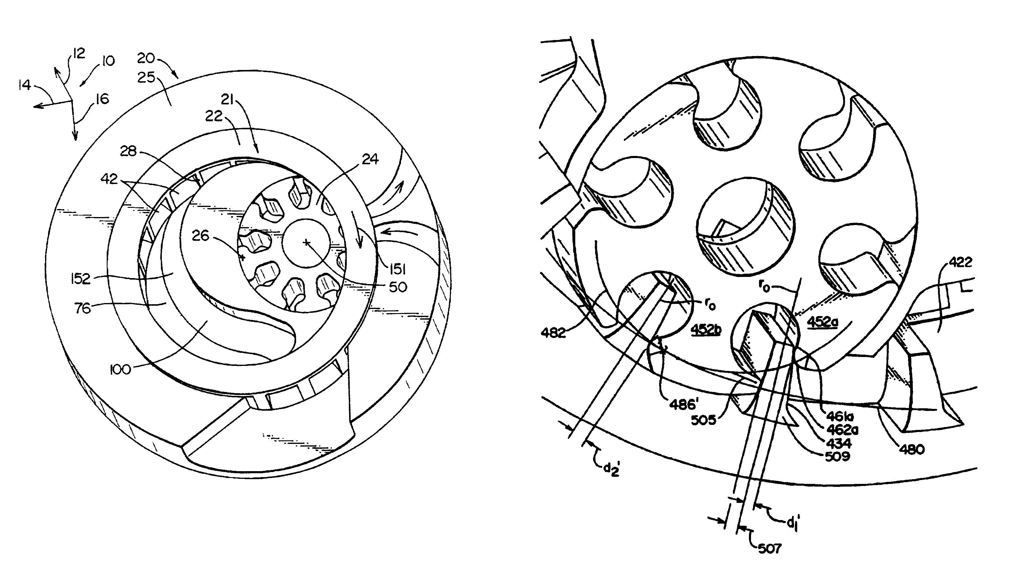
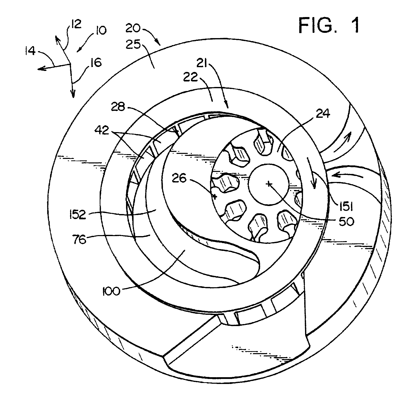
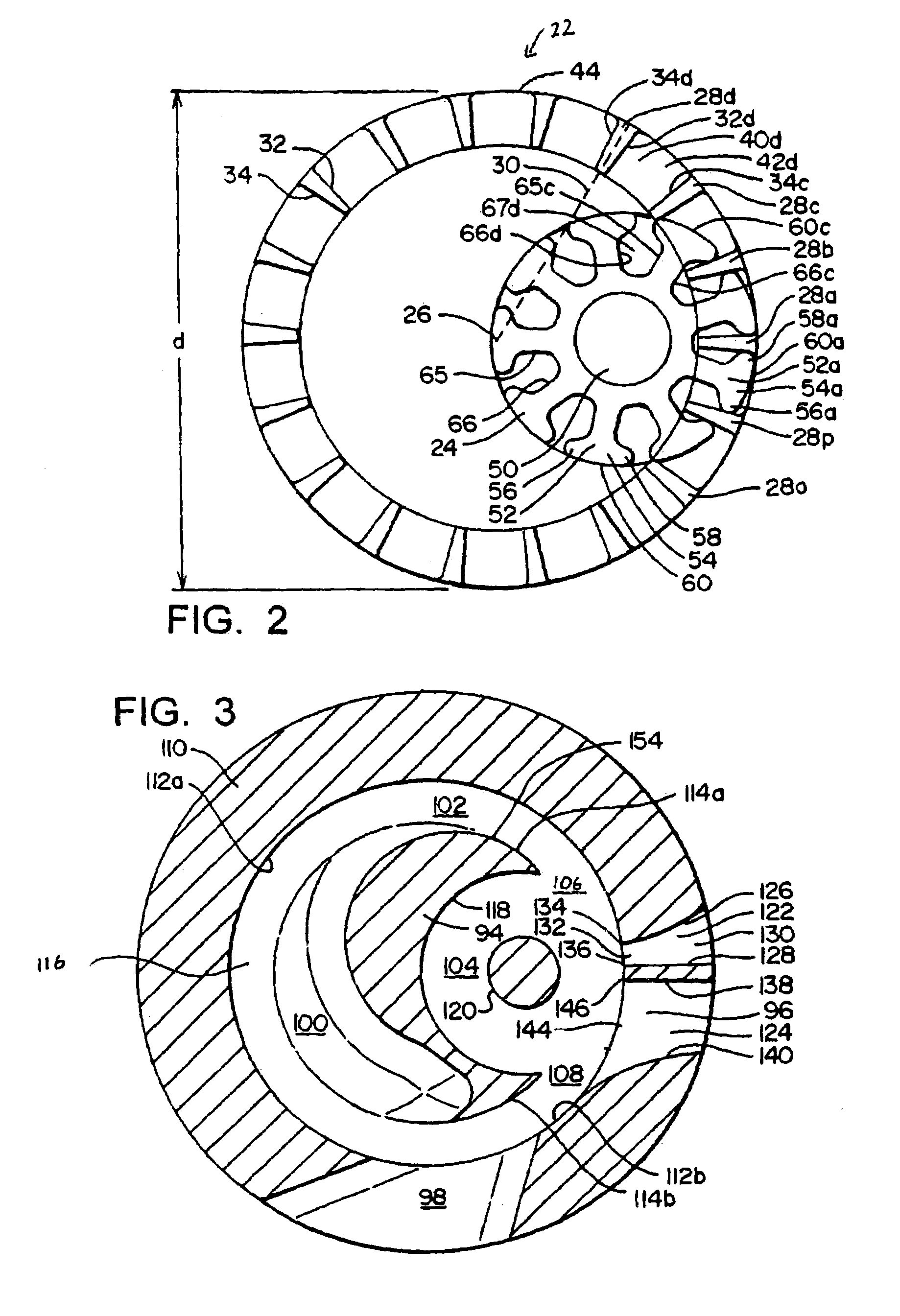
[0048]As seen in FIG. 1, there is shown the apparatus 20 comprising a rotor assembly 21 and a housing 25. Shown in FIG. 1, the rotor assembly 21 comprises an outer rotor 22, and an inner rotor 24. The outer rotor 22 has an outside diameter d (FIG. 2) and a center point indicated at 26 that indicates the location of the axis of rotation for the outer rotor 22. The outer rotor further has a plurality of fins 28 discussed further herein. As shown in FIG. 10, the outside rotor further has an outer reference circle 80 and the inner rotor 24 has an inner reference circle 82 that is one half of the diameter of the outer reference circle 80. The significance of this geometrical integer ratio requirement is discussed further herein.

[0049]Now referring back to FIG. 2, the fins 28 each have a central axis 30 that extends through the center point 26. The fins 28 further comprise a forward surface 32 and a rearward surface 34. It should be noted that surfaces of 32 and 34 are substantially flat ...

second embodiment

[0078]In general, the second embodiment discloses an external combustion engine where a second rotor assembly 223 is employed to receive exhaust gas from a combustion chamber 227. The second outer rotor 245 is connected to the outer rotor 228 so both rotate in conjunction with one another. The exhaust exiting the combustion chamber 227 is of greater volume than the exhaust entering through passage 229 and is greater volume is channeled into the expansion chambers 250 and 251 of the first and second rotor assemblies 221 and 223. A portion of the output work of the second rotor assembly 223 is used to compress the air exiting the exit passage 253 of the first rotor assembly that is directed into the combustion chamber 229. The remainder of the work output of the second rotor assembly 223 can be displaced into an output shaft attached to the outer rotor 255. Alternatively, compressed air exiting the exit passage of the second rotor assembly 223 can be utilized for a “cold blow” discuss...

fourth embodiment

[0107]Further, the outer rotor has 18 fins and the inner rotors have six legs (a ratio of 3-1). It should be noted that although the fourth embodiment discloses four interior rotors 424, there can be one—four interior rotors. However, having four interior rotors as particular benefits of balancing the force upon the central shaft described further herein.

[0108]The rotor 422 further comprises a scoop region 431 best shown in FIG. 19 which shows the backside of one of the rotor assembly support 420 of FIG. 18. As seen in FIG. 19, the scoop region 431 comprises a plurality of vanes 433 define channels 435 that channel the air radially inward to the longitudinal extensions 437. Now referring to FIG. 18, the extensions 437 channel air into the chambers 442. The scoop region 431 is connected to and can be a unitary structure with the outer rotor 422. FIG. 18 shows an embodiment where two apparatuses 420 are positioned in a back-to-back arrangement having two outer rotors 422 and eight inn...


PUM


Abstract

A device to convert energy having exterior and interior rotors where the number of legs (Λ) of an interior rotor divided by the number of chambers (X) defined by the fins of the outer rotor is equal to the effective radius of the inner reference circle ri divided by the effective radius of the outer reference circle ro (i.e. Λ / X=ri / ro). Where the surface of the fins of the outer rotor and the toe and heel portion of the interior rotor allow for a sealed chamber for a finite amount of rotation of the inner and outer rotors.

Description

[0001]This application claims the benefit of priority from provisional application Ser. No. 60 / 267,969 filed Feb. 8, 2001, which application is incorporated by reference herein-in its entirety.FIELD OF INVENTION[0002]The invention relates to rotary motion positive displacement devices having interior rotors that have extensions that engage inner chamber regions of an outer rotor.BACKGROUND[0003]Reciprocating motion of piston engines and positive displacement compressors have mechanical limitations on their maximum rotations per minute due to the stresses and wear incurred by reciprocating motion. Other rotary motion positive displacement devices that have rotors on parallel axes of rotation such as shown in U.S. Pat. No. 3,850,150 employ a plurality of interior rotors, however, the spurs of the interior rotors are not adapted to engage either end of the recesses of the outer rotor simultaneously for more than a single point of rotation. Therefore it is not possible to have a sealed ...

Claims


Application Information

Patent Timeline
Patent Type & Authority Patents(United States)
IPC IPC(8): F02B53/00F01C1/10F01C1/08F01C11/00
CPCF01C1/084F01C1/102F01C11/002F01C11/004F01C1/103F02B2053/005
Inventor KLASSEN, JAMES B.
Owner SPARTAN HLDG
Why Eureka
Try Eureka