Weaving machine and method for weaving pile fabrics and spacer for such a weaving machine

a weaving machine and pile fabric technology, applied in weaving, textiles and papermaking, looms, etc., can solve the problems of increasing the tension of yarn, increasing the risk of yarn breaking, and becoming difficult, if not impossible, to supply pile warp yarns

Active Publication Date: 2006-09-26
VAN DE WIELE MICHEL
View PDF9 Cites 17 Cited by
  • Summary
  • Abstract
  • Description
  • Claims
  • Application Information

AI Technical Summary

Problems solved by technology

Because of this, the tension of the yarn will be increased, but most of all will cause problems and the risk of yarn breaks.
In case the weaving machine is equipped with lancets, it becomes difficult, if not impossible, to supply the pile warp yarns when the fabric is formed, not in a single selection position to form the shed of these pile warp yarns, these yarns may come in contact with the lancet holder.
Such a contact may conduce to a greater tension to be built up and to an increased wear of the pile warp yarns.
Causing an increase of the risk of yarn breakage, which may cause machine downtime and fabrics of an inferior quality.
This means an increase of the load on the shed forming device and may cause an inaccurate or incorrect formation of the shed and an increased energy consumption.
A further disadvantage consists in the fact that a motion from a position in which there is a contact with the lancet holder to a position without any contact with the lancet holder, causing the yarn to be returned to the weaving creel, this returning of yarn will be greater when the pile warp yarn is in touch with the lancet holder, than when the pile warp yarn is not in touch with the lancet holder.
This has a particularly harmful influence on the return springs of the harness.
This will conduce to pile warp yarns being no longer tensioned for a short period, which has an adverse effect on the weaving process.
Finally, this may cause pile warp yarns and harness cords to get entangled, which finally may cause machine downtime, so that important manual interventions may be required.
The resulting shock load on the return springs will cause in turn a shorter life of these return springs.
These problems will become the greater as the operating speeds will be increased, the shed required to operate the machine is increasing and the number of pile warp yarns will be increased (more colors or higher densities).
Up to the present, these so-called spoon lancets are taken up in one central lancet holder, having the disadvantage that these lancets, because of their weight at the top, are sagging and are difficult to install.
The suspension thus obtained is rather unstable.

Method used


Image

  • Weaving machine and method for weaving pile fabrics and spacer for such a weaving machine
  • Weaving machine and method for weaving pile fabrics and spacer for such a weaving machine
  • Weaving machine and method for weaving pile fabrics and spacer for such a weaving machine

Examples


Embodiment Construction

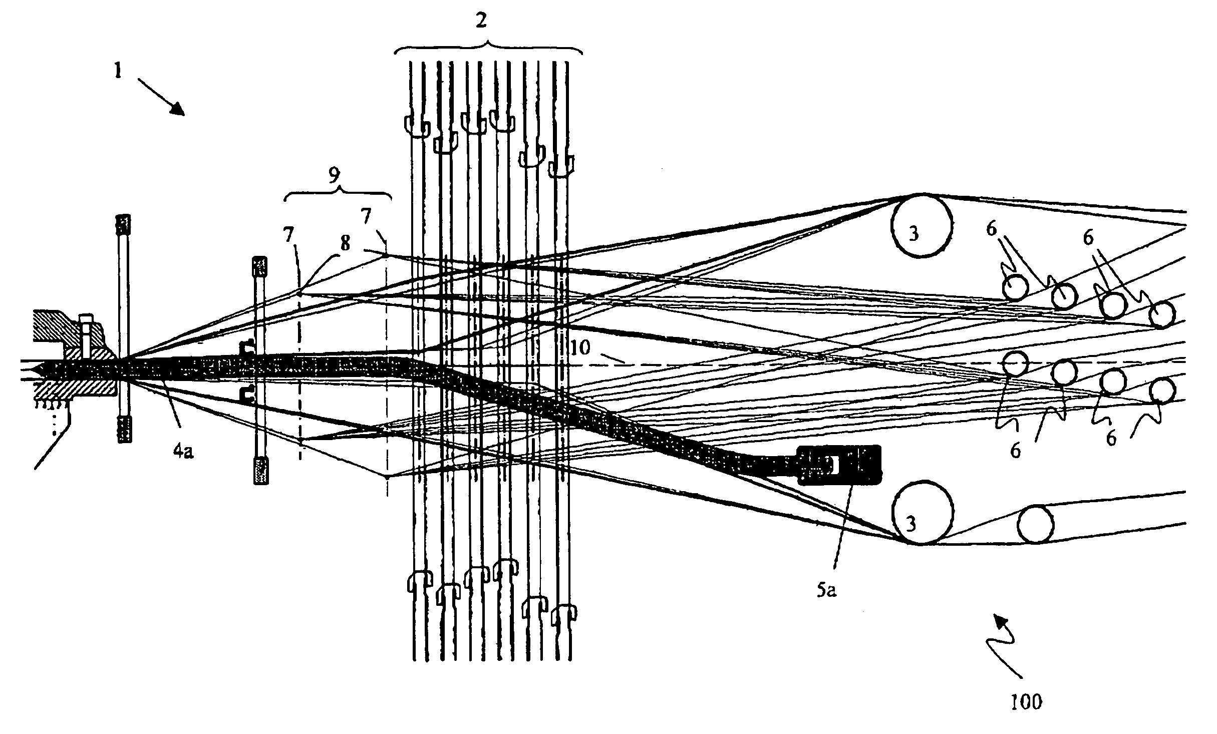
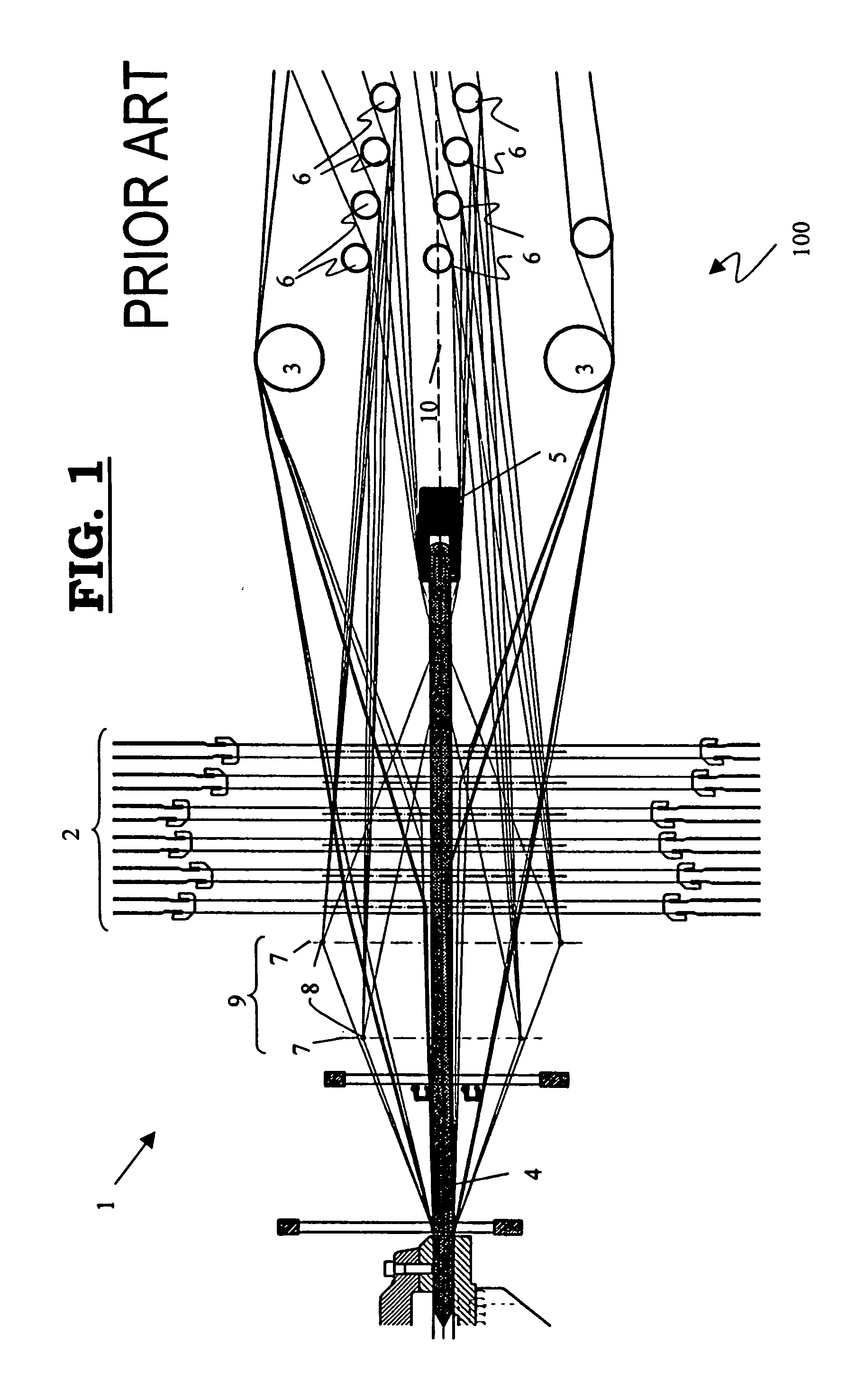
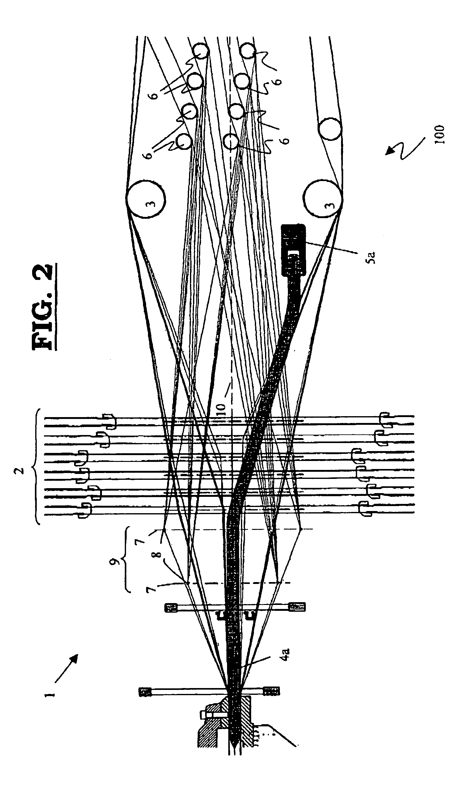
[0078]In a weaving machine (1) for weaving pile fabrics consisting of weft yarns, backing warp yarns and pile warp yarns, for example a face-to-face weaving machine as represented in the FIGS. 1 through 6, the warp yarns are supplied from the rear (100) of the weaving machine (1). The warp yarns being brought into the required positions by the shed forming elements in order to realize the shed needed to form the pattern required for the backing and pile fabrics. The backing and pile warp yarns therefore are extending through one or several shed forming devices which have been provided with one or several heddle frames (2) moving up and down and containing a set of heddles (7), distributed across the width of the weaving machine (1). By means of these heddles (7), the backing warp yarns in the shed, i.e. the binding and tension warp yarns to form the backing fabric for the upper and lower fabric are brought into the positions required in accordance with the weave structure desired. E...


PUM


Abstract

A weaving machine weaves pile fabrics having weft yarns, backing warp yarns, and pile warp yarns. One or several spacers extend between the pile warp yarns either to realize a constant pile height between two pile fabrics formed, or to determine the pile loop height in one or several pile fabrics comprising pile loops. One or several holders clamp the spacers. One or several shed forming devices, drive heddles through which backing and/or pile warp yarns extend to position these warp yarns with respect to the weft yarns. A zone for supplying pile warp yarns extends between a yam supply and the heddles. One or several holders installed between the yarn supply and the one or several shed forming devices clamp the spacers. The holders are installed outside the said supply zone, in such a manner that the pile warp yarns will extend into the supply zone without any hindrance.

Description

[0001]This application claims the benefit of Belgian Application No. 2004 / 0107 filed Feb. 25, 2004 and Belgian Application No. 2004 / 0319 filed Jun. 28, 2004 which are hereby incorporated by reference in their entirety.BACKGROUND OF THE INVENTION[0002]The invention firstly relates to a weaving machine for weaving pile fabrics consisting of weft yarns, backing warp yarns and pile warp yarns comprising:[0003]one or several spacers extending between the pile warp yarns and which are provided either to realize a constant pile height between two pile fabrics formed, or to determine the pile loop height in one or several pile fabrics comprising pile loops;[0004]one or several holders for clamping the spacers;[0005]one or several shed forming devices, driving heddles through which backing and / or pile warp yarns extend in order to position these warp yarns with respect to the weft yarns;[0006]a yarn supply;a zone for supplying pile warp yarns extending between the yarn supply and the heddles...

Claims


Application Information

Patent Timeline
Patent Type & Authority Patents(United States)
IPC IPC(8): D03D39/16
CPCD03D39/16
Inventor DEBAES, JOHNY
Owner VAN DE WIELE MICHEL
Why Eureka
Try Eureka