
Slide coupling fitting for connecting conduits

a technology of coupling fittings and connecting conduits, which is applied in the direction of flush cleaning, lighting and heating apparatus, heating types, etc., can solve the problems of difficult threading of conduits, limited access and mobility, and time-consuming and laborious problems

Inactive Publication Date: 2006-09-26
COOGLE GREGORY
View PDF16 Cites 27 Cited by
  • Summary
  • Abstract
  • Description
  • Claims
  • Application Information

AI Technical Summary

Benefits of technology

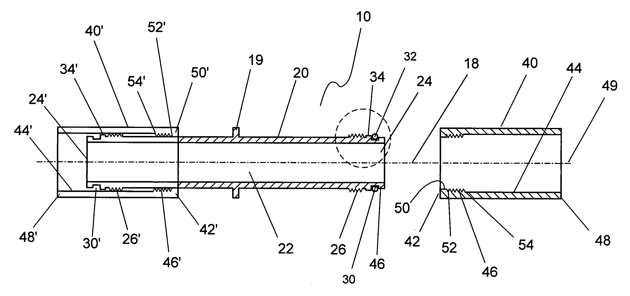
[0009]Furthermore, each of the tubular sliding couplers further comprises an internal block section extending about a central axis of the tubular sliding couplers. The external block section of the tubular body and the internal block section of the sliding coupler assist positioning of the sliding coupler along the tubular body when engaging the internal threaded section with the external threaded section.

Problems solved by technology

For fluid flow conduits, they are frequently buried underground, and have limited access and mobility during repairing.
One of the swedging members is placed on the interior of the tubular conduit which results in a restriction which is smaller than the interior diameter of the tubular conduit, rather than providing a full bore opening.
A threaded connection requires the threading of either an interior surface or an exterior surface of the tubular conduit, which is time consuming and labor intensive.
For the buried conduits, threading the conduits becomes very difficult, sometimes, is not feasible at all.
However, these structures completely depend on adhesive bonding, therefore, have poor resistance to environmental temperature variations.

Method used


Image

  • Slide coupling fitting for connecting conduits
  • Slide coupling fitting for connecting conduits
  • Slide coupling fitting for connecting conduits

Examples


Embodiment Construction

[0027]In one embodiment, the present invention provides a slide coupling fitting which has two tubular sliding couplers for slidably connecting the fitting between two tubular conduits.

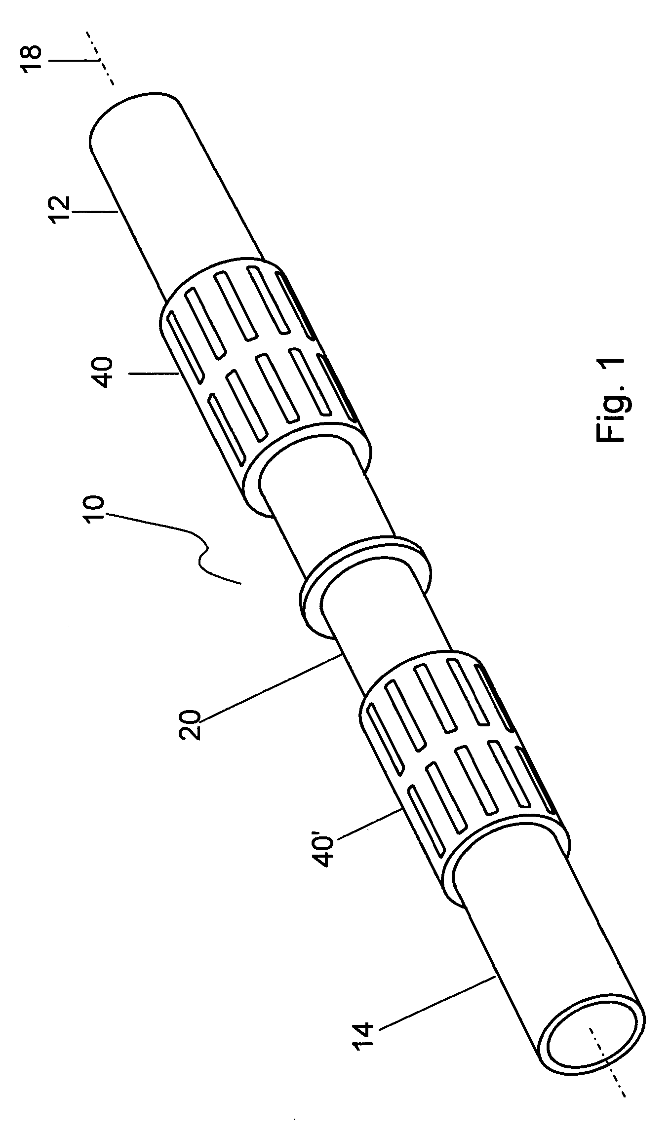
[0028]Referring now to FIG. 1, there is illustrated a perspective view of a slide coupling fitting 10 for joining to a tubular conduit 12 and a tubular conduit 14. The tubular conduits 12 and 14 are commonly used pipes, which are usually made of PVC or other plastic pipe materials, and have smooth exterior peripheries. Commonly used tubular conduits 12 and 14 range in size from one-half inch to six inches in diameter. The fitting 10, tubular conduit 12 and tubular conduit 14 are coaxially aligned along a central axis 18.

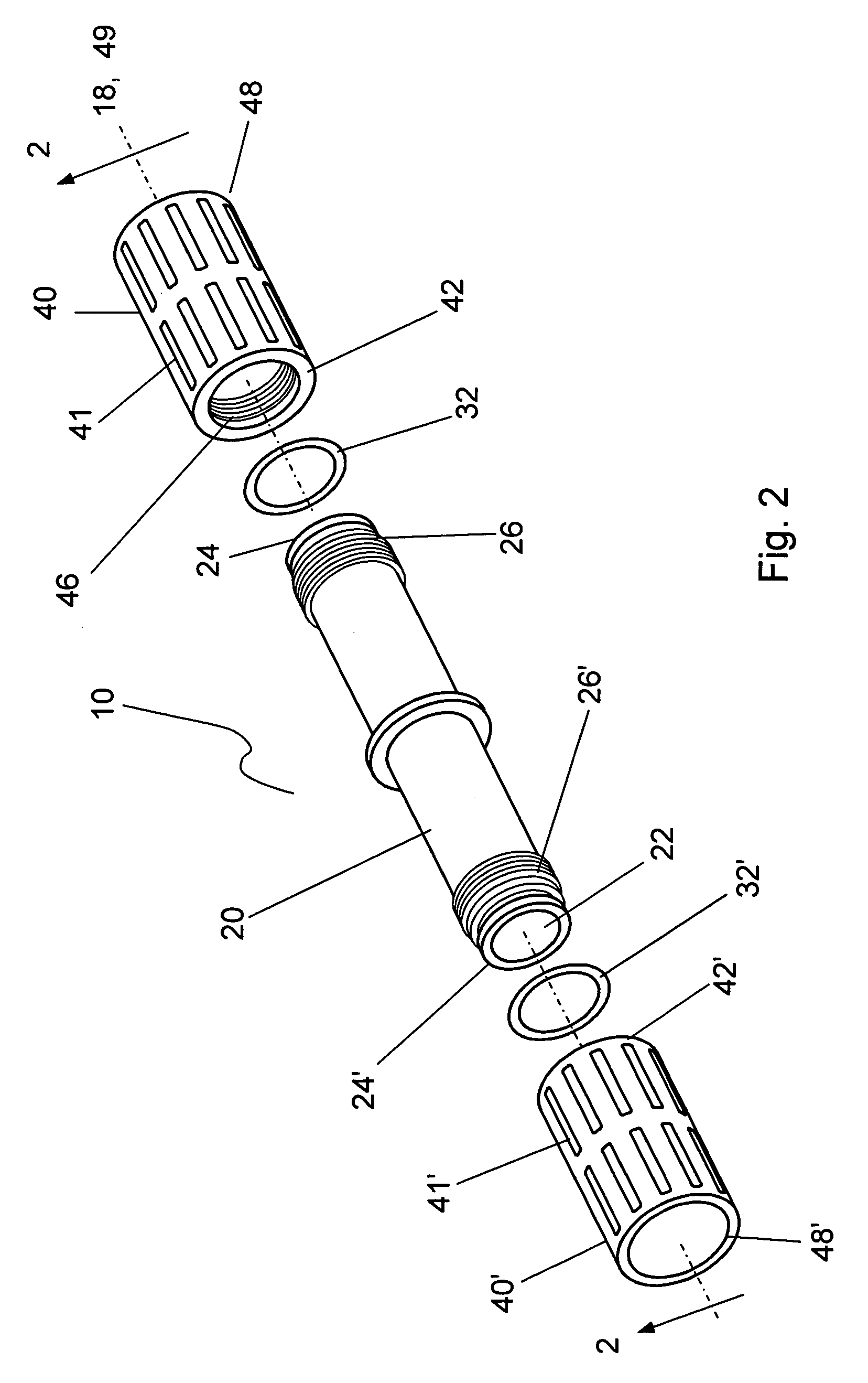
[0029]Referring now to FIGS. 2 thru 3A, slide coupling fitting 10 comprises a tubular body 20 having a central passage 22 defining central axis 18, two opposing open ends 24 and 24′, and two external threaded sections 26 and 26′ on an exterior of tubular body 20; wherein external threa...


PUM


Abstract

A slide coupling fitting for connecting a tubular conduit and the method of use are provided. The fitting includes a tubular body, two opposing open ends, and an external threaded section on an exterior of the tubular body adjacent to each open end; and two tubular sliding couplers, each having an internal diameter slightly larger than an external diameter of the tubular body, and each being connected to one of the open ends of the tubular body, respectively, and coaxial with the tubular body. Each tubular sliding coupler has an internal threaded section adjacent to an inner end which is closer to a longitudinal center of the tubular body, and a smooth interior at an opposing outer end for slidably engaging a tubular conduit. The internal threaded section is complementary to the external threaded section of the tubular body for mutual engagement.

Description

REFERENCE TO RELATED APPLICATION[0001]This application is a continuation-in-part of patent application Ser. No. 10 / 144,113, filed May 10, 2002, now U.S. Pat. No. 6,708,717, which is herein incorporated by reference in its entirety.FIELD OF THE INVENTION[0002]The present invention relates in general to connectors for tubular conduits, and in particular to fittings which has both a threaded connection section and a sliding connection section for slidably coupling to the ends of conduit.BACKGROUND OF THE INVENTION[0003]Prior art connectors and fittings have been utilized for joining to tubular conduits for connecting the tubular conduits together or to other members. The tubular conduits have included piping, ducting, electrical conduits and the like, which have been used for both fluid flow conduits and to provide protective enclosures for electrical power and telecommunication cables. For fluid flow conduits, they are frequently buried underground, and have limited access and mobilit...

Claims


Application Information

Patent Timeline
IPC IPC(8): F16L27/12B08B9/02B08B9/032F24F13/22F28G9/00
CPCB08B9/0321F28G9/00F24F13/222Y10T137/2567Y10T137/3127Y10T137/4259
Inventor COOGLE, GREGORY
Owner COOGLE GREGORY
Learn More