Milling cutter

a technology of cutters and cutting boards, applied in the field of milling cutters, can solve the problems of time-consuming screw use and screw exposur

Active Publication Date: 2006-09-26
ISCAR LTD
View PDF12 Cites 10 Cited by
  • Summary
  • Abstract
  • Description
  • Claims
  • Application Information

AI Technical Summary

Benefits of technology

[0045]It will be appreciated that the present invention not only provides a particularly efficient way of changing adapters in accordance with the diameter of the spindle support shaft, but at the same time facilitates increasing the depth of cut of the milling cutter.
[0046]Although the present invention has been described to a certain degree of particularity, it should be understood that various alterations and modifications could be made without departing from the scope of the invention as hereinafter claimed.

Problems solved by technology

The use of screws is time consuming and may be disadvantageous in that rotative motion is imparted by the hub to the cutter body via the screws, thereby exposing the screws to shear forces which could damage them.

Method used


Image

  • Milling cutter
  • Milling cutter
  • Milling cutter

Examples


Embodiment Construction

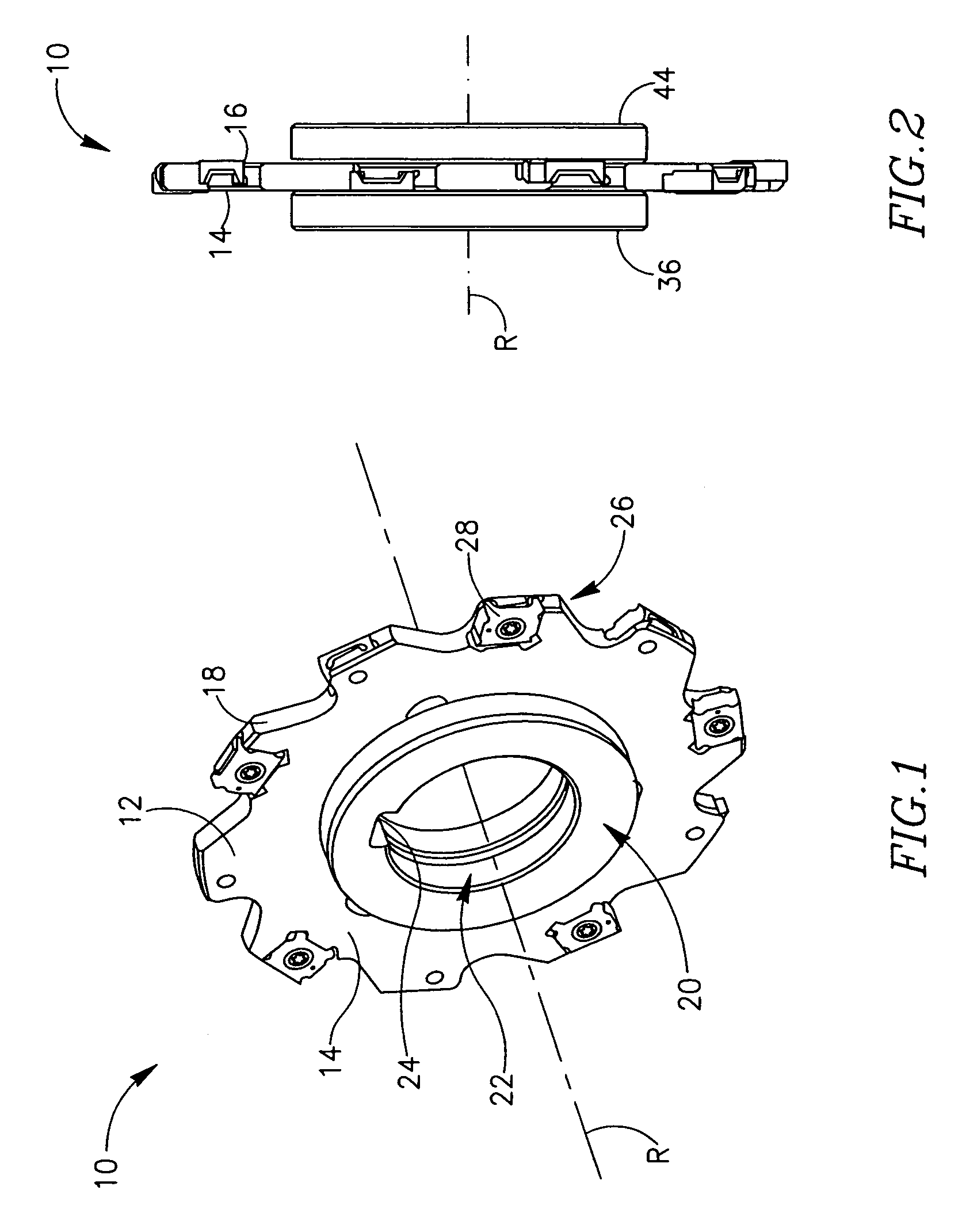
[0033]Attention is drawn to FIGS. 1 and 2, showing a milling cutter 10 in accordance with the present invention. The milling cutter 10 has a generally disk-shaped cutter body 12, having first and second opposing, generally parallel, side surfaces 14, 16 and an outer peripheral surface 18 extending between the two side surfaces 14, 16. The milling cutter 10 has an axis of rotation R which is perpendicular to the two side surfaces 14, 16. The milling cutter 10 has a hub 20 with an axially centered hole 22 for receipt of a support shaft of a machine spindle (not shown). Rotative motion is imparted to the hub 20 of the cutter via a drive key (also not shown) which mates with drive keyway 24. A plurality of circumferentially spaced apart cutting portions 26 are located around the outer peripheral surface 18 of the cutter body 12, each cutting portion 26 being provided with a cutting insert 28.

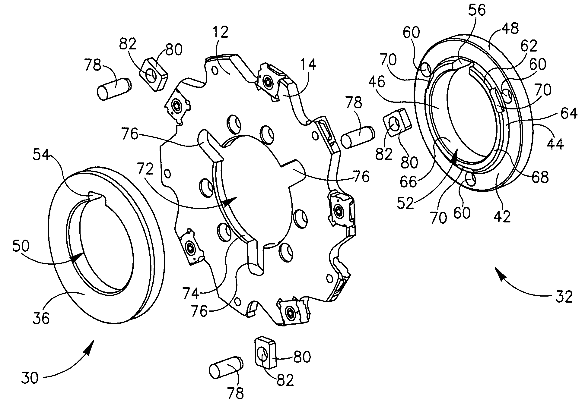
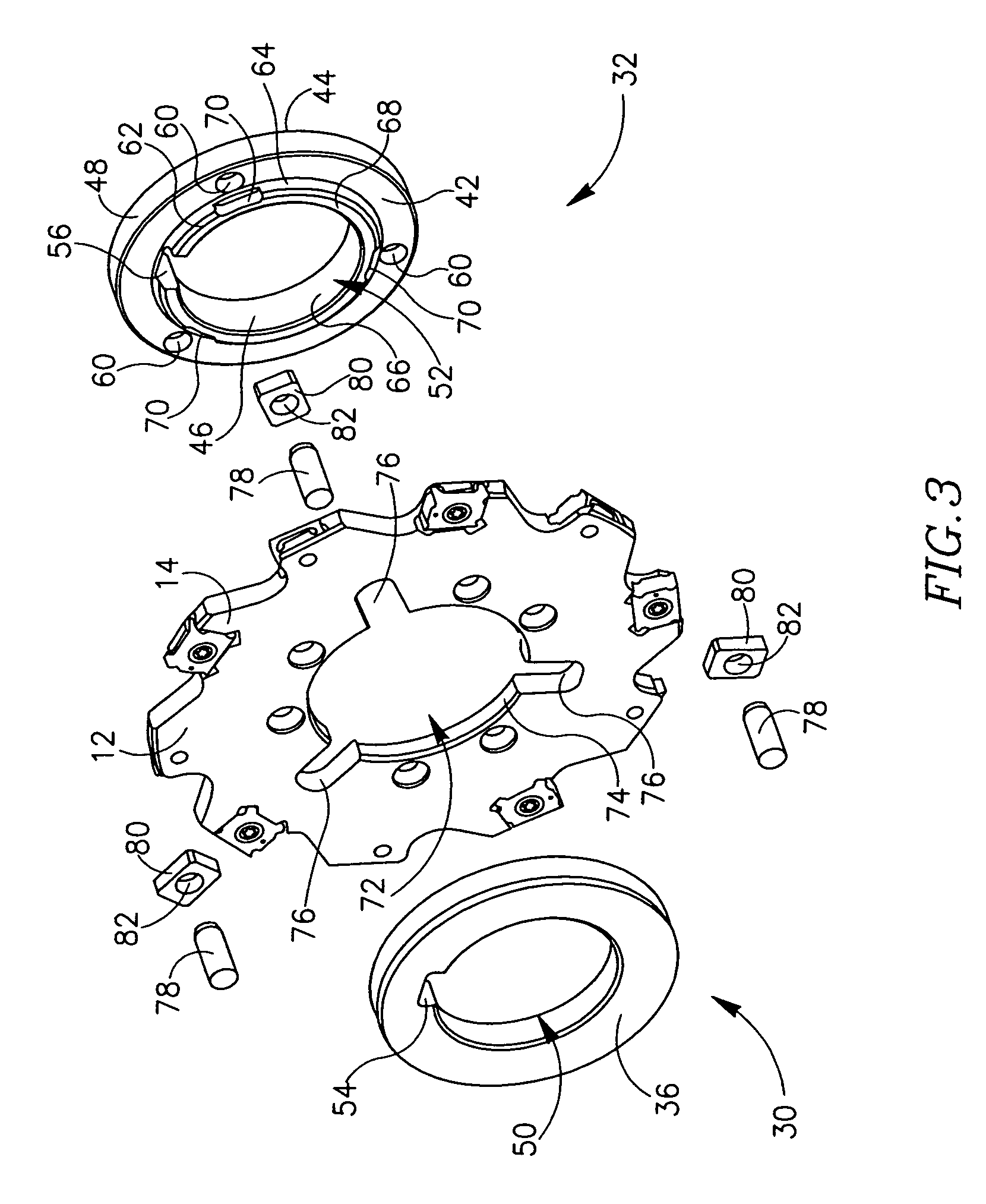
[0034]Attention is now additionally drawn to FIGS. 3 and 4. The hub 20 comprises first and secon...


PUM

PropertyMeasurementUnit
of rotationaaaaaaaaaa
shapeaaaaaaaaaa
shapesaaaaaaaaaa

Abstract

A milling cutter with a disk like cutter body having radially directed slots and a central aperture. An exchangeable hub comprises two adapter members located on either side of the cutter body. One of the adapter members has a raised portion located in the central aperture. The adapter members are secured to the cutter body by means of pins which are located in blind holes in the adapter members and which pass through engagement members positioned in the slots.

Description

FIELD OF THE INVENTION[0001]The present invention relates to milling cutters and in particular to milling cutters with disk like cutter bodies.BACKGROUND OF THE INVENTION[0002]Such milling cutters are typically used for slotting operations and have a hub with an axially centered hole for receipt of a support shaft of a machine spindle. Since the hole has a given diameter, the milling cutter can only be used with a shaft of a given diameter.[0003]It is an object of the present invention to provide a milling cutter with an exchangeable hub. For such a milling cutter, hubs can be prepared with any required hole diameter. When it is required to use the milling cutter with a support shaft having a diameter different from that of the hole diameter, the hub which is attached to the cutter body can be removed and a new hub with the required diameter can be attached to the cutter body in its place. Milling cutters with exchangeable hubs are known, however they generally employ screws (or bol...

Claims


Application Information

Patent Timeline
Patent Type & Authority Patents(United States)
IPC IPC(8): B23C1/00
CPCB23C5/006B23C5/08B23D61/026B23C2200/367Y10T407/1906Y10T407/1936Y10T407/1944Y10T407/22Y10T29/49826Y10T407/2202Y10T83/9326
Inventor SATRAN, AMIREISEN, YARON
Owner ISCAR LTD
Why Eureka
Try Eureka