Cutting tool configured for improved engagement with a tool holder

a technology of cutting tools and tool holders, which is applied in the field of cutting tools, can solve the problems of another drawback of the arrangement of tools and holders

Inactive Publication Date: 2006-09-26
KENNAMETAL INC
View PDF24 Cites 31 Cited by
  • Summary
  • Abstract
  • Description
  • Claims
  • Application Information

AI Technical Summary

Benefits of technology

[0007]Generally speaking, the invention is directed to a cutting tool that has a shank with a cylindrical portion that is adapted to fit equal to or more closely within a tool holder. The shank is adapted to be engaged by a setscrew of the tool holder at a first contact point. A clearance surface is provided opposite the first contact point. The clearance surface terminates adjacent two circumferentially spaced points that make contact with the tool holder upon tightening the setscrew. These contact points are circumferentially spaced from the first contact point angular distances greater than 90 degrees and less than 270 degrees.

Problems solved by technology

The aforementioned tool and holder arrangement has another drawback.

Method used


Image

  • Cutting tool configured for improved engagement with a tool holder
  • Cutting tool configured for improved engagement with a tool holder
  • Cutting tool configured for improved engagement with a tool holder

Examples


Embodiment Construction

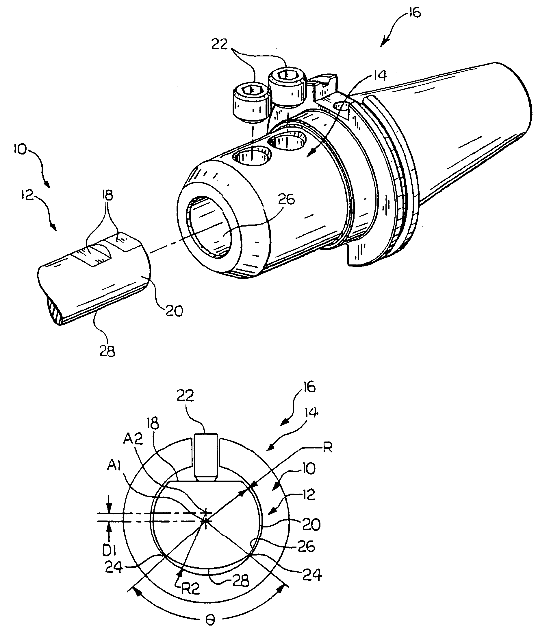
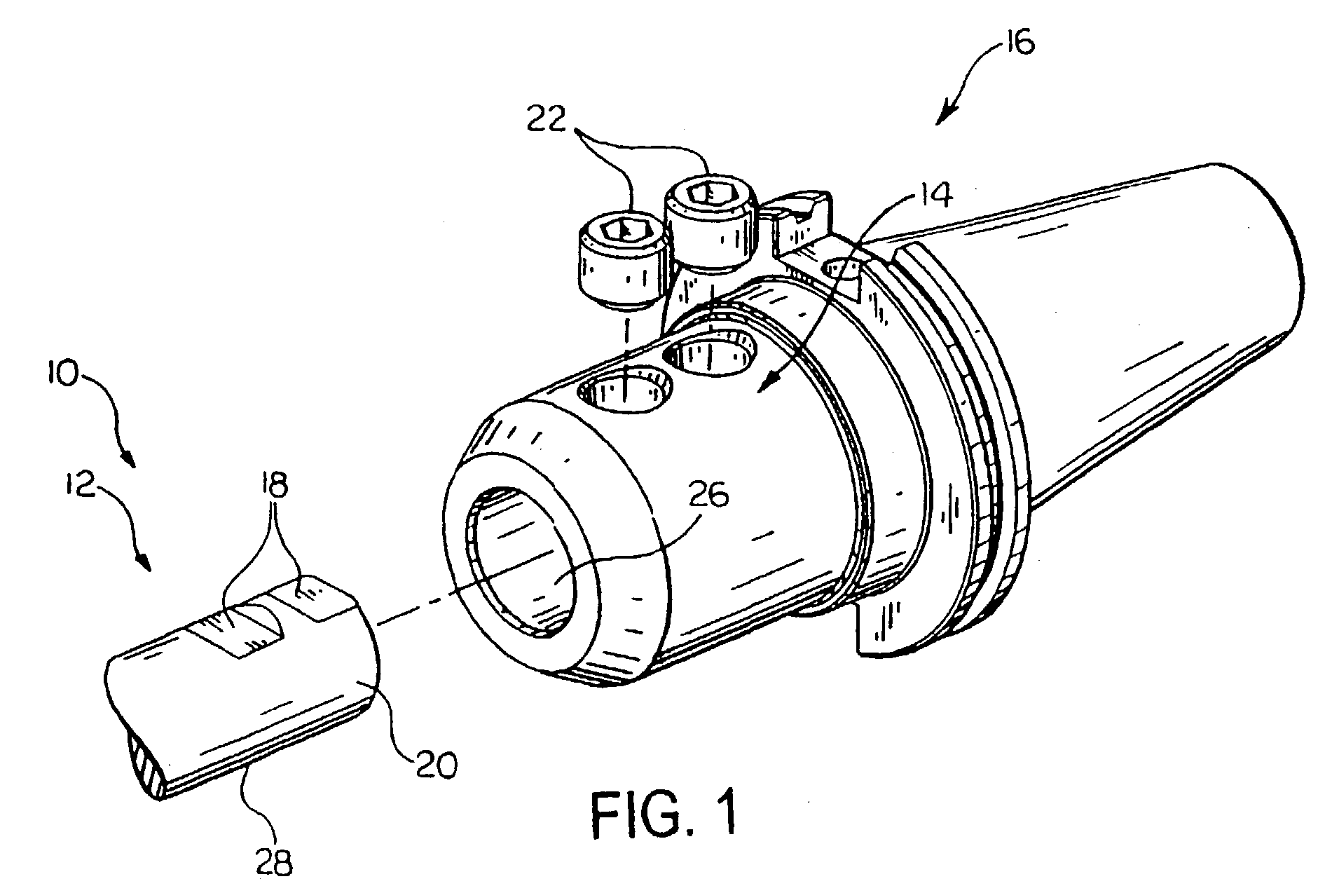
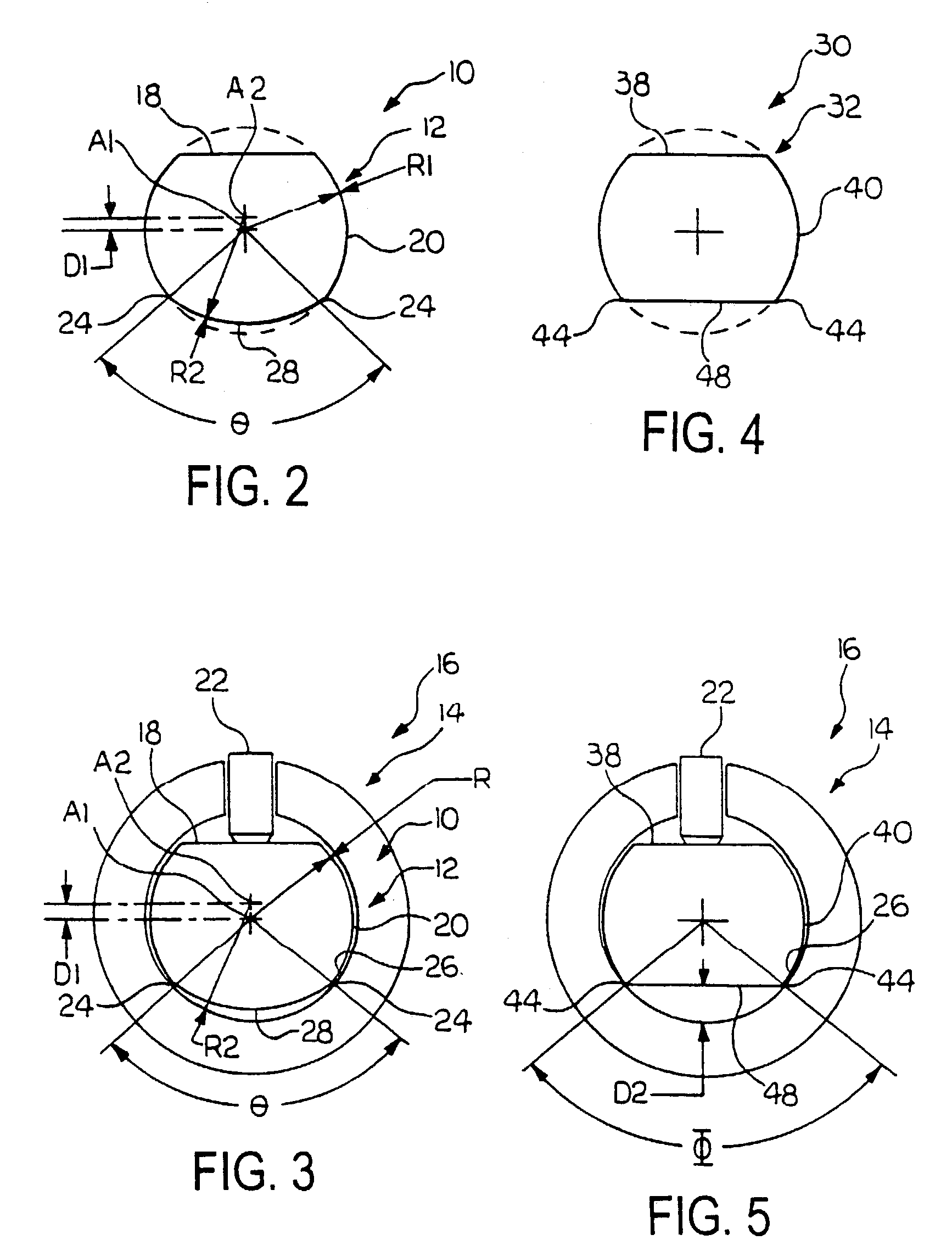
[0014]With reference now to the drawings, wherein like numerals designate like components throughout all of the several figures, there is illustrated in FIG. 1 a cutting tool 10 according to one embodiment of the invention. The cutting tool 10 has a shank 12 that has one or more substantially cylindrical portions, or a predominantly cylindrical peripheral surface 20. The shank 12 has a specific diameter that mates with, fits closely within, or fits within a close tolerance (e.g., about 0.001 to about 0.005 inch) of a substantially cylindrical adapter or sleeve member 14 of a tool holder 16. The tool holder 16 is mounted to the spindle of a power drive unit (not shown) and is adapted to support the cutting tool 10 in order to connect the cutting tool 10 to the power drive unit.

[0015]The shank 12 may be provided with one or more flats 18, which may be machined, or otherwise provided, along one side of the peripheral surface 20 of the shank 12. In accordance with a preferred embodiment...


PUM

PropertyMeasurementUnit
specific diameteraaaaaaaaaa
angleaaaaaaaaaa
angleaaaaaaaaaa

Abstract

A cutting tool has a shank with a cylindrical portion that is adapted to fit closely within a tool holder. The shank is adapted to be engaged by a setscrew of the tool holder at a first contact point. A clearance surface is provided opposite the first contact point. The clearance surface terminates adjacent two circumferentially spaced points that make contact with the tool holder upon tightening the setscrew. These contact points are circumferentially spaced from the first contact point angular distances greater than 90 degrees and less than 270 degrees.

Description

FIELD OF THE INVENTION[0001]The present invention relates to a cutting tool and, more particularly, to the cooperative engagement of a cutting tool and a tool holder. Most particularly, the invention relates to an improved cutting tool structure that cooperates with a tool holder to minimize vibration during a milling operation that results in chatter.BACKGROUND OF THE INVENTION[0002]Metal working machines are well known. A conventional metal working machine typically includes a power drive unit, such as an electric, hydraulic, or pneumatic motor; a suitable cutting tool, such as a drill, boring tool, probe or the like; and a tool holder for connecting the cutting tool to the power drive unit. The tool holder typically includes a socket or sleeve member, which is mounted directly to the power drive unit, and which is adapted to support the cutting tool in order to connect the cutting tool to the power drive unit.[0003]A typical cutting tool has a cylindrical shank with a specific di...

Claims


Application Information

Patent Timeline
Patent Type & Authority Patents(United States)
IPC IPC(8): B23C5/00B23BB23B31/00B23B31/107
CPCB23B31/005B23B31/1075B23B2231/0252Y10T408/95Y10T409/30952Y10T279/17821Y10T408/907B23B2231/0256
Inventor SHEFFLER, GLENN W.DE SOUZA, FILHO RUY FROTA
Owner KENNAMETAL INC
Why Eureka
Try Eureka