
Self-calibration method and apparatus for on-axis rotary encoders

a self-calibration method and encoder technology, applied in the direction of speed/acceleration/shock measurement, speed measurement using gyroscopic effects, instruments, etc., can solve the problem of limited accuracy, the number of calibration points is limited by the polygon facet, and the method cannot be directly applied to calibrate general encoders with a single read-head

Inactive Publication Date: 2009-01-29
THE UNIV OF BRITISH COLUMBIA
View PDF6 Cites 20 Cited by
  • Summary
  • Abstract
  • Description
  • Claims
  • Application Information

AI Technical Summary

Benefits of technology

[0013]f) establishing an encoder error map using the selected solved angular distances from the model.
[0014]Additional steps to the method can include: selecting a plurality of data set pairs from the output signals in step (c); solving the model for the angular distances for each of the plurality of data set pairs in step (e); then in step (f): calculating the repeatability of the ...

Problems solved by technology

However, the number of calibration points is limited by the polygon facet number.
As this system requires the index table to unlock and lock down at every tooth position, it is time-consuming and the accuracy is limited by both the index table and the interferometer.
In all the above references, self-calibration methods were developed for special encoder and spindle setups (typically using multiple read-heads), but these methods cannot be directly applied to calibrate general encoders with a single read-head.
However, the calibration result can only be applied to the speed used in calibration.
However, it is impractical to control the spindle speed accurately enough for calibration purposes, due to imbalance, feedback sensor errors, and motor driving torque ripple.

Method used


Image

  • Self-calibration method and apparatus for on-axis rotary encoders
  • Self-calibration method and apparatus for on-axis rotary encoders
  • Self-calibration method and apparatus for on-axis rotary encoders

Examples


Embodiment Construction

[0074]The embodiments of the present invention relate to a self-calibration method and apparatus for on-axis rotary encoders, and a rotary encoder calibrated by such method and apparatus.

[0075]Rotary Encoder Apparatus and Rotary Encoder Calibration System

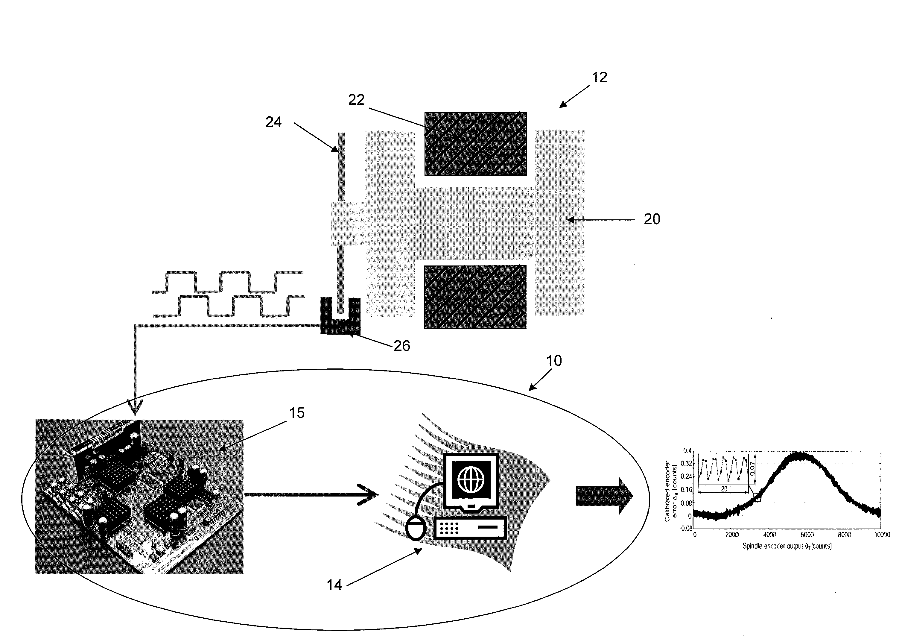
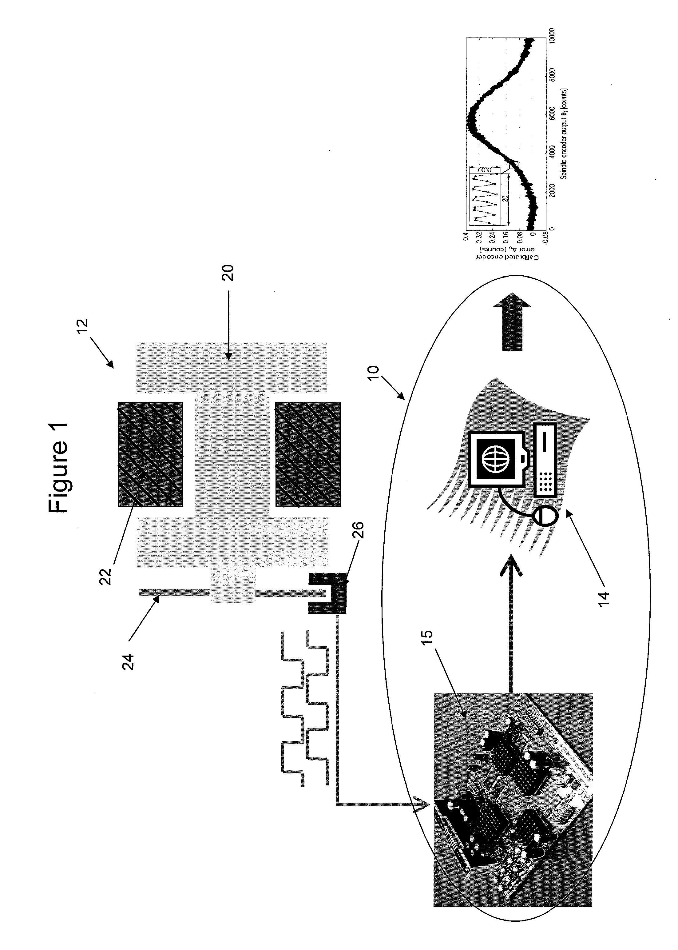
[0076]Referring to FIG. 1, a rotary encoder calibration system 10 for calibrating a rotary encoder 12 generally comprises: a timer 15 communicative with the encoder 12; and a processor 14 communicative with the timer 15 and having encoded thereon a self-calibration algorithm.

[0077]The rotary encoder 12 is part of a motorized spindle which also comprises a rotor 20, a stator 22, and a motor (not shown) coupled to the rotor 20 and operable to rotate the rotor 20 relative to the stationary stator 22. Such a spindle is known in the art and can be for example a Professional Instrument 4R Twin-mount motorized air bearing spindle. The rotary encoder 12 provides high accuracy positional measurement in various types of machinery, including u...


PUM


Abstract

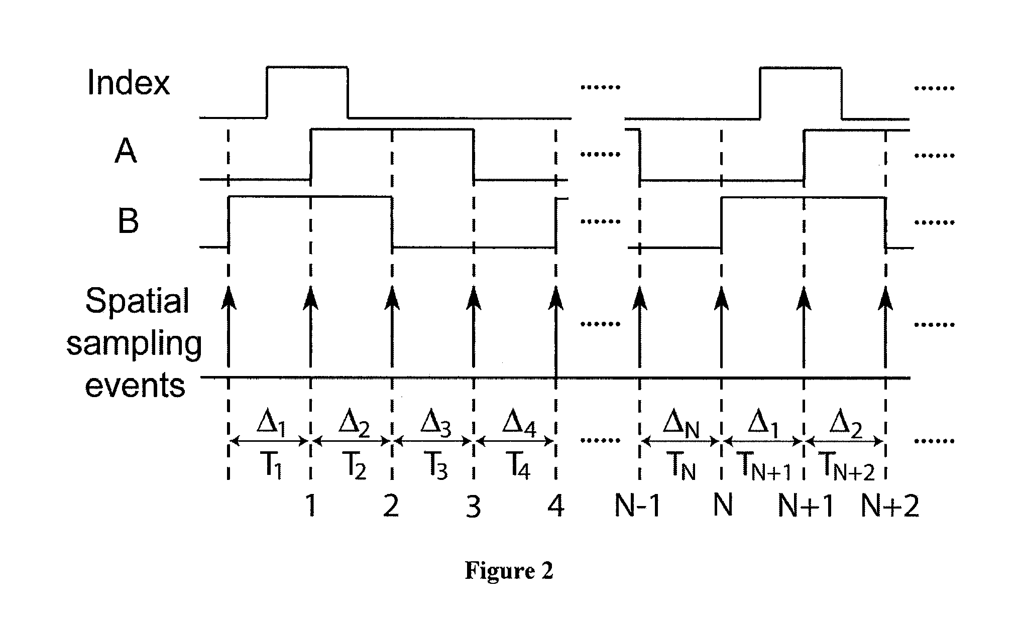
A self-calibration method and apparatus for on-axis rotary encoders comprising the steps of: receiving output signals from a detector during a spindle-free response period, the signals including a plurality of data sets wherein each data set comprises the periods between sampling events occurring in one revolution of the encoder at an angular speed, selecting a data set pair from the output signals, wherein the data set pair contains two linearly uncorrelated data sets; defining a model of the angular distances between each sampling event occurring in one revolution of the encoder as a function of one or more damping coefficients and the periods between each sampling event as contained in the data set pair; solving the model for the angular distances for the data set pair using circular closure and dynamic reversal techniques; and establishing an encoder error map using the selected solved angular distances from the model.

Description

FIELD OF INVENTION[0001]The present invention relates to a self-calibration method and apparatus for on-axis rotary encoders, and apparatus calibrated by such method and apparatus.BACKGROUND OF THE INVENTION[0002]High-accuracy angular encoders are widely used for rotational axis position measurement in ultra-precision manufacturing equipment and measurement instruments, such as diamond turning machines for free-form optical surface generation. A typical rotary encoder is made of a glass disk with a fine grating pattern and a scanning read head unit. Digital pulse trains are output from the read head to represent the disk rotary position. The angular measurement accuracy of such a rotary encoder is highly dependent on the grating pattern manufacturing error (uniformity and eccentricity of the graduation), encoder disk installation eccentricity on the rotary axis, read head alignment, and so on. Repeatable components of encoder error can in principle be eliminated through calibration ...

Claims


Application Information

Patent Timeline
IPC IPC(8): G01P21/00
CPCG01D5/24452G01P21/02G01D5/2449G01D18/001
Inventor LU, XIAODONG
Owner THE UNIV OF BRITISH COLUMBIA
Learn More