Fractal impeller for stirring

a fractal impeller and impeller technology, applied in the field of impellers, can solve the problems of inability to achieve inability to use the impeller, and inability to achieve the uniform spatial distribution of energy in the conventional strs, so as to achieve low shear, improve mixing, and reduce power consumption

Inactive Publication Date: 2013-08-15
COUNCIL OF SCI & IND RES
View PDF21 Cites 19 Cited by
  • Summary
  • Abstract
  • Description
  • Claims
  • Application Information

AI Technical Summary

Benefits of technology

[0011]Another objective of the present invention is to provide an efficient impeller to achieve uniformity throughout the stirred tank and can yield better mixing and low shear at relatively low power consumption.
[0012]In accordance with the above, the invention discloses a new impeller that occupies less than 0.4% of the volume of the reactor, which is similar to the conventional impeller system, but spreads, over almost the entire vessel, yielding a structure with relatively large voids. Accordingly, the instant invention provides an impeller with fractal design to a...

Problems solved by technology

The energy requirement of these processes forms a significant part of the total energy and contributes toward major expenses.
However turbulence inducing mechanical mixing devices, such as impellers, blenders, impinging devices, is not used in the U.S. '882.
Thus, uniform spatial di...

Method used


Image

  • Fractal impeller for stirring
  • Fractal impeller for stirring
  • Fractal impeller for stirring

Examples


example 1

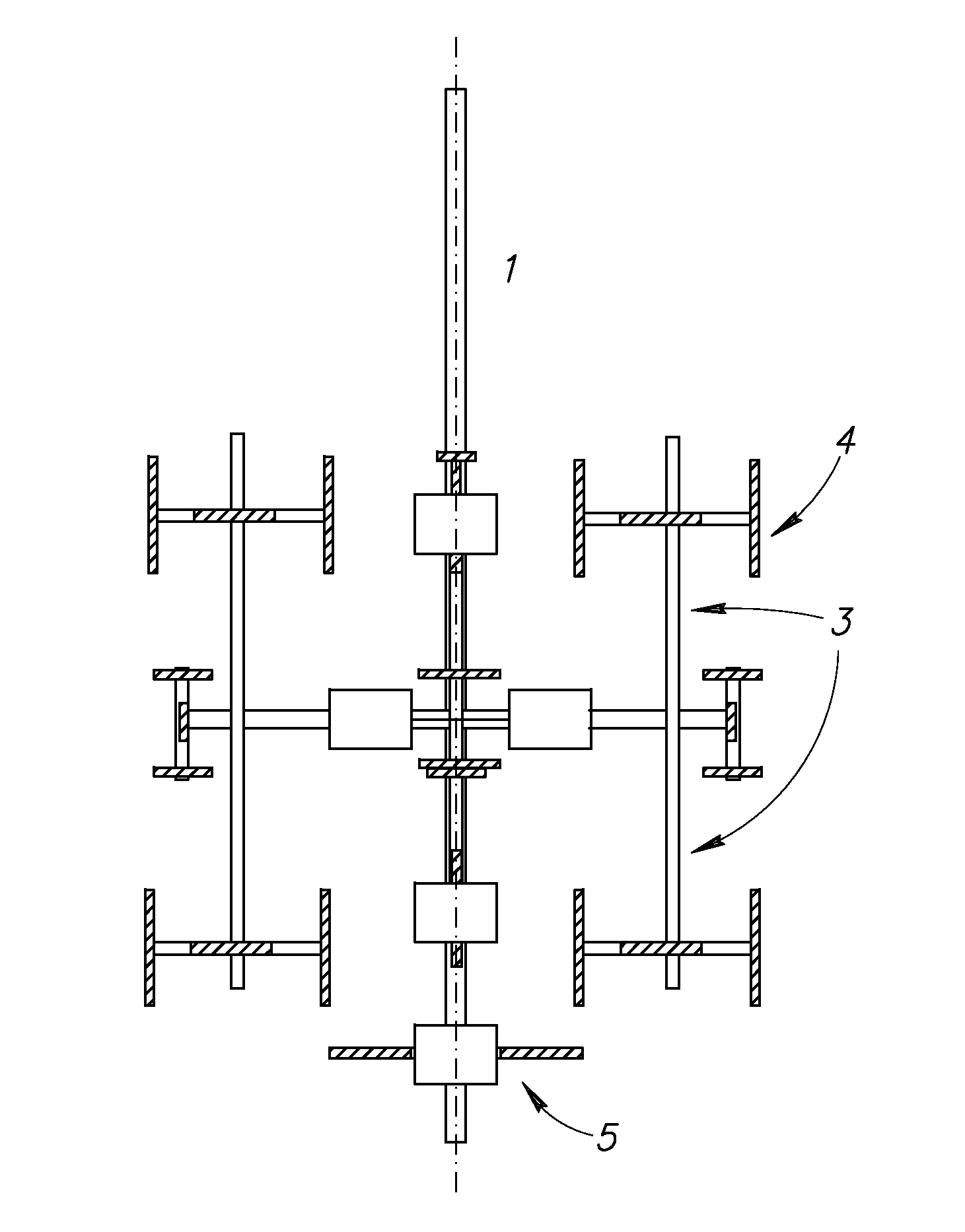
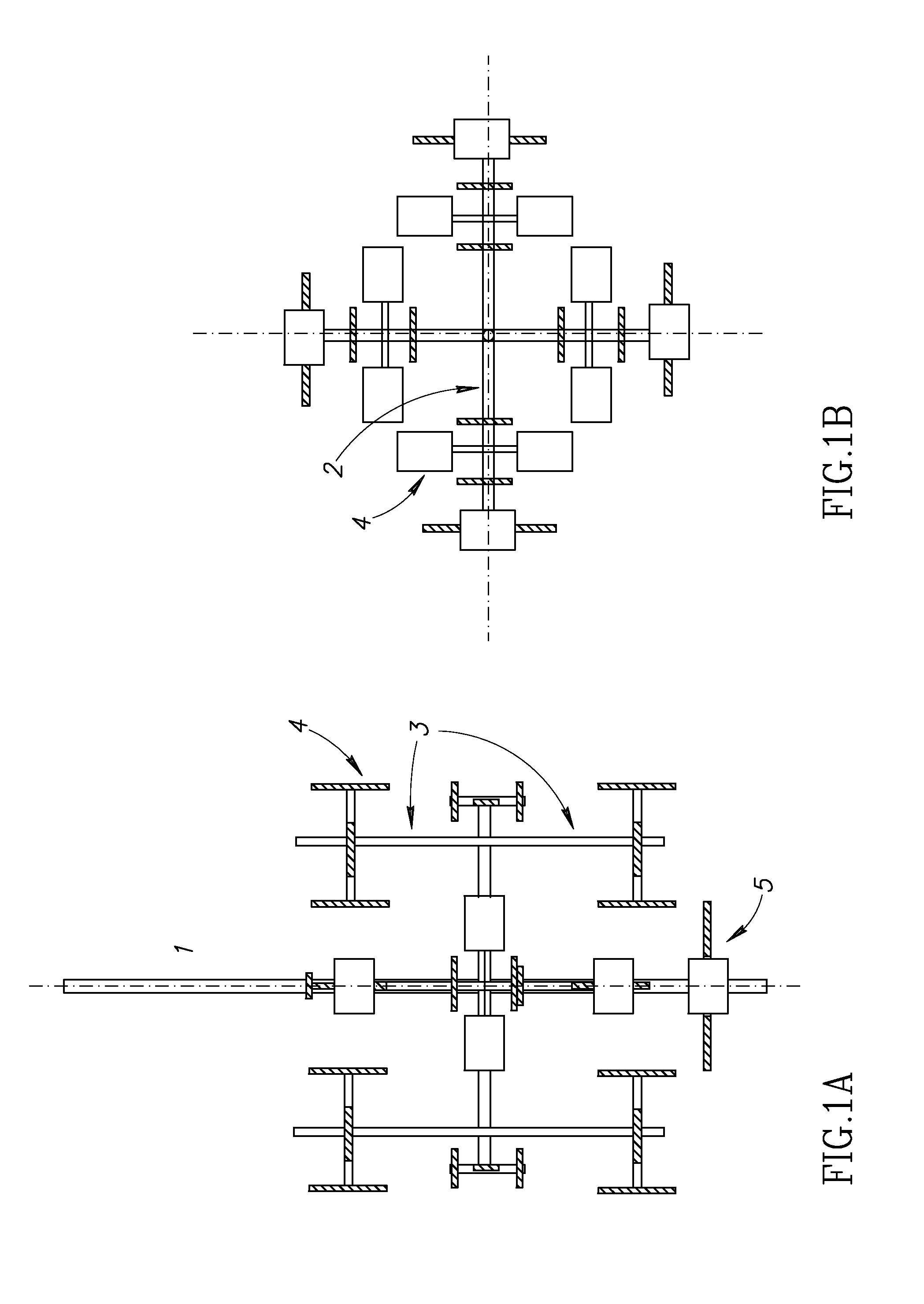
[0038]The experiments were carried out in an acrylic stirred tank (T=H=0.3 m) with a single impeller system. The vessel was fitted with four baffles (width, W=T / 10). The impeller shaft was connected to a DC motor via a shaft mounted torque transducer. Experiments were carried out with three different impellers: 6 blade-disk turbine (DT), 6 blade—pitched blade down flow turbine (PBTD), and the fractal impeller (FI). For DT and PBTD, the impeller diameter was D=T / 3=100 mm, and the off-bottom clearance (C) was equal to T / 3. The FI was supported from the bottom by making a counter groove on the shaft (FIG. 1D) and for the FI, diameter of fractal impeller (DFI)=T / 1.58. A steel ball (6 mm diameter) was sandwiched between the bottom of the shaft and the center of the vessel bottom. The volume of the liquid inside the reactor was 21.2 L for all experiments. The solidity of all the impellers was maintained in a close range.

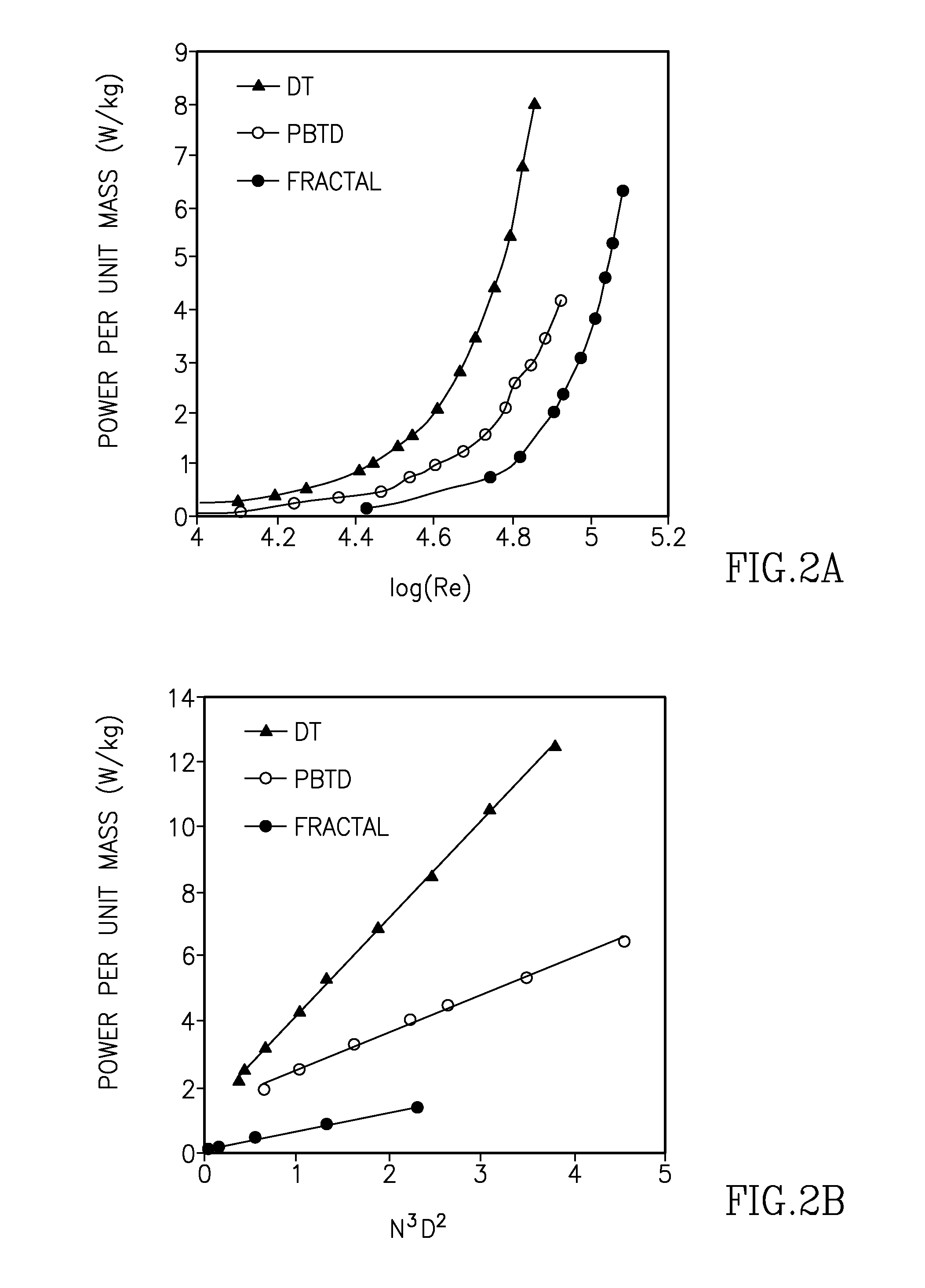
[0039]The experiments were carried out to compare the performance of ...


PUM


Abstract

A fractal impeller design for stirred tank reactors comprising plurality of main branches, each of which further having plurality of sub-branches with each sub branch having plurality of blades to distribute/dissipate energy in uniform manner and to achieve uniform temperature throughout the reactor while operating it at lower impeller speed to avoid high shear zones; wherein, the angular distances covered by the blades vary and yield variation in the local blade passage velocity for a given impeller rotation speed.

Description

FIELD OF THE INVENTION[0001]The present invention relates to impellers used in stirred tank reactors. More particularly, the present invention relates to fractal impeller which reduces the non-uniformity of the reaction mass and develops uniform randomness throughout the reactor.BACKGROUND OF THE INVENTION[0002]Stirred tank reactors (STR) form an integral component of chemical, pharmaceutical, and the fermentation industry. These types of reactors are in operation for last several decades and a number of investigators have analyzed them in detail to optimize the designs based on the power consumption, mass and heat transfer, and the internal hydrodynamics. In the stirred reactors, the energy is supplied in the form of a kinetic energy by rotating the impeller at desired speed. STRs are largely used for (i) mixing or blending of two miscible liquids, (ii) generation of dispersions for gas-liquid and liquid-liquid reactions, (iii) keeping the solid particles in suspension to facilitat...

Claims


Application Information

Patent Timeline
IPC IPC(8): B01F7/00B01F27/96
CPCB01F7/32B01F27/96
Inventor KULKARNI, AMOL A.KULKARNI, BHASKAR DATTTRAYA
Owner COUNCIL OF SCI & IND RES
Why Eureka
Try Eureka