Brushless DC electric motor

a brushless, electric motor technology, applied in the direction of machines/engines, magnetic circuit rotating parts, magnetic circuit shape/form/construction, etc., can solve the problems of difficult manufacturing of known devices and large space occupation of combinations, and achieve the effect of reducing the overall height of the devi

Inactive Publication Date: 2006-09-26
ADVANCED ROTARY SYST
View PDF24 Cites 69 Cited by
  • Summary
  • Abstract
  • Description
  • Claims
  • Application Information

AI Technical Summary

Benefits of technology

[0005]It is an object of the present invention to provide a new brushless DC electric motor and integrated brushless DC electric motor / blower or motor / pump combination as two possible configurations of this design. This electric motor in combination with an impeller for blowers or pumps is capable of significantly reducing an overall height thereof.

Problems solved by technology

The known device is not easy in manufacturing, the biggest difficulty being manufacturing of disk-shaped rotors with magnetic poles of alternating polarity.
Prior art motor-fans combinations occupy a large space because of the two separate components, the motor and impeller.

Method used


Image

  • Brushless DC electric motor
  • Brushless DC electric motor
  • Brushless DC electric motor

Examples


Embodiment Construction

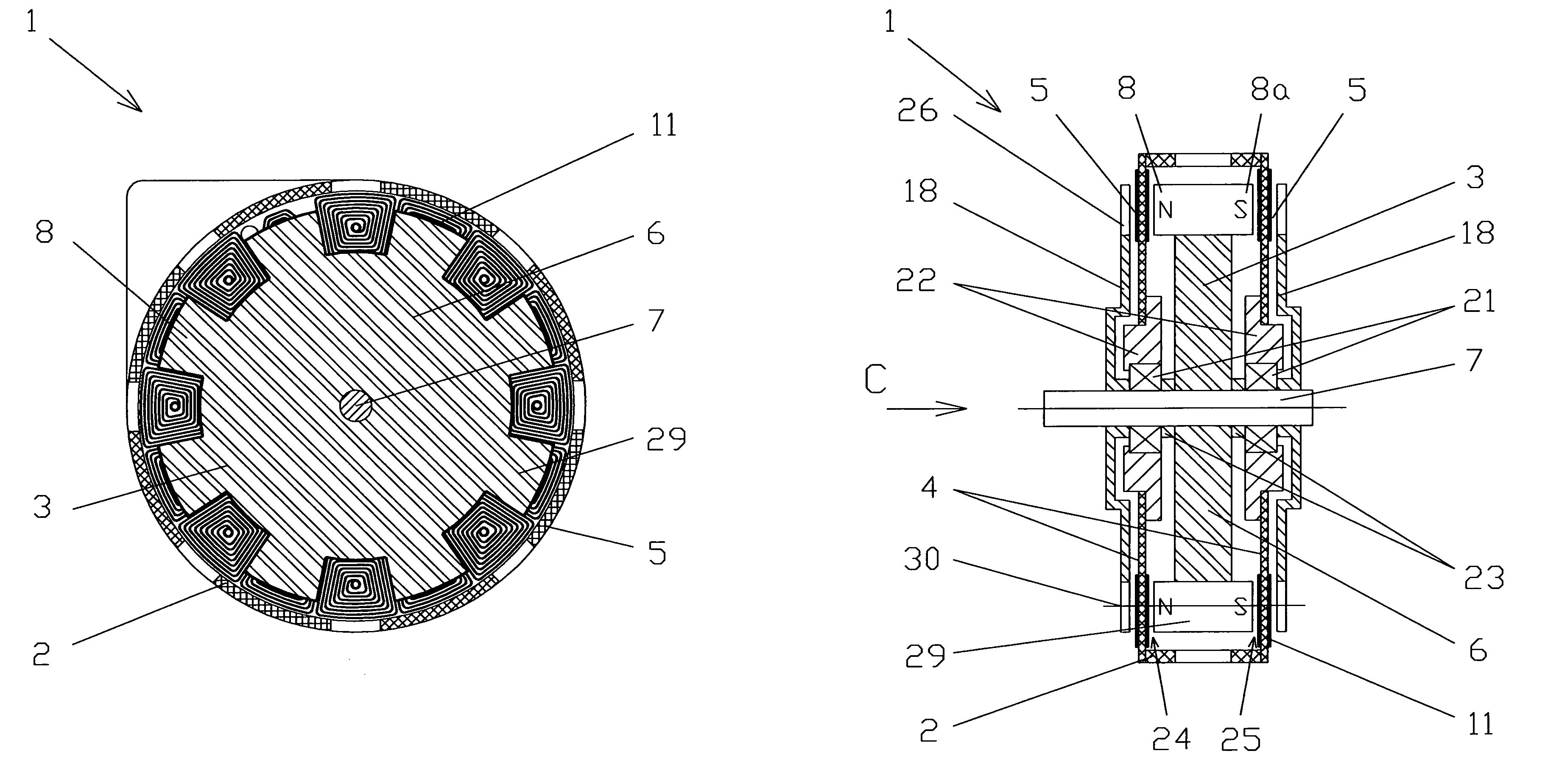
[0016]The following is a description of a new brushless DC electric motor design using printed circuit boards for coil windings. We will refer to these printed circuit boards hereafter as circuit boards throughout this description. The magnetic rotor is made of a permanent magnet material and may be a monolithic part or an assembly having like magnetic poles. This monolithic part or assembly will be referred to hereafter as a magnetic rotor or blower impeller. The following brief description is broken into six parts: Circuit Board, Magnetic Rotor, Motor Description, Integrated Motor / Blower, Controlling Device and Operation Description.

[0017]Circuit Board

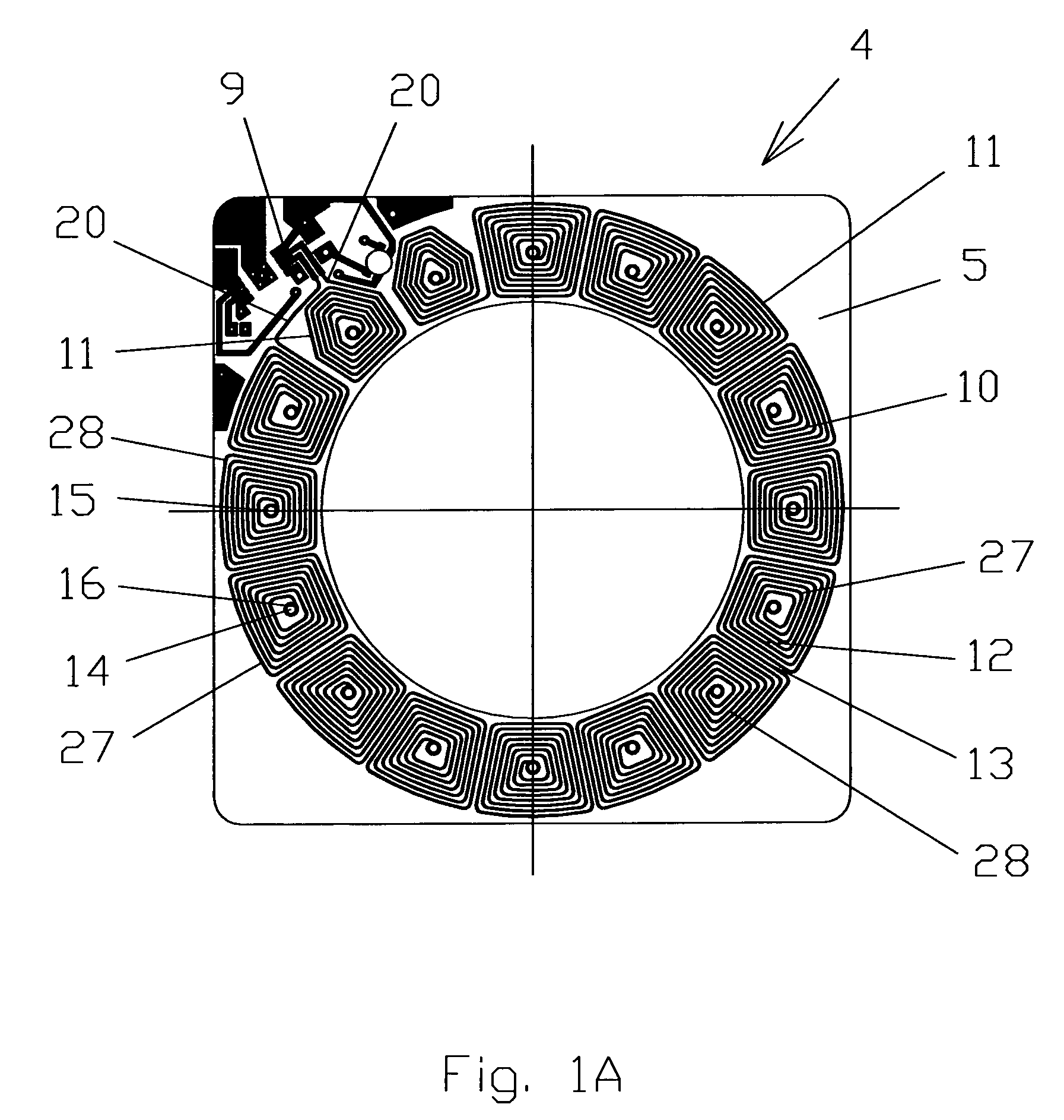
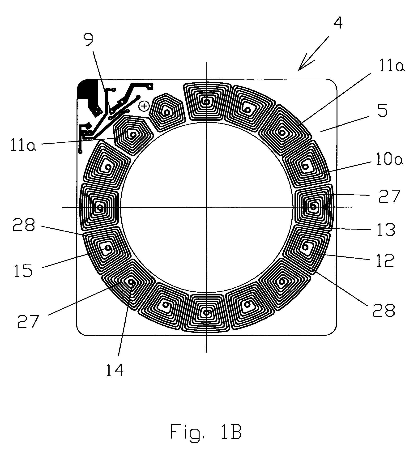
[0018]This described circuit board is constructed for use with an H-Bridge Drive controller. FIG. 1A illustrates a front side of a stator 4 that contains coil windings 11 etched from metal, usually copper, on a circuit board 5 and located around the circumference of the stator 4. FIG. 1B illustrates a back (transparent) side of the s...


PUM


Abstract

An electric motor comprises a housing, a magnetic rotor and a stator which comprises at least one circuit board. The magnetic rotor comprises a disk with circumferentially arrayed magnetic poles. The circuit board on each side comprises one layer of circumferentially arrayed coil windings arranged in pairs, thus each pair made as a spiral that extends from a center of a start coil winding to a center of an end coil winding with the same turn direction of the spiral in relation to each of centers. The layers are the same in transparent view and shifted angularly in such a way thus centers of the start coil windings from one side of the circuit board coincided and electrically connected by via's with centers of the end coil windings on the other side of the circuit board.

Description

CROSS-REFERENCE TO RELATED APPLICATIONS[0001]The present application claims the benefits of priority of the U.S. Provisional Patent Application Ser. No. 60 / 301,229 filed Jun. 26, 2001 for Edward Lopatinsky et al. the entire content of which is incorporated herein by reference.FIELD OF THE INVENTION[0002]The invention is related to electric engineering, and in particular electromagnetic machines, and may be used in the manufacture of electric drives for various purposes, e.g. ventilation, compressors, pumps, wheels of electrically driven automobiles etc.BACKGROUND OF THE INVENTION[0003]Well-known are machines of end-face rotor-stator interaction type, where the rotor is a disk, on the end surfaces whereof permanent magnets of alternating polarity are located over the circumference. The stator of such machines is made in the shape of a disk (ring), installed coaxially with the rotor, electromagnetic stator coils being located at the end faces of the stator. For instance, the direct cu...

Claims


Application Information

Patent Timeline
Patent Type & Authority Patents(United States)
IPC IPC(8): H02K3/26H02K1/27H02K7/14H02K21/24H02K29/00
CPCH02K1/2793H02K3/26H02K21/24H02K7/14Y10S310/06H02K2211/03F04D25/0653H02K1/2795
Inventor LOPATINSKY, EDWARDSCHAEFER, DANIELROSENFELD, SAVELYFEDOSEYEV, LEV
Owner ADVANCED ROTARY SYST
Why Eureka
Try Eureka