Liquid crystal display device

a display device and liquid crystal technology, applied in the field of liquid crystal display devices, can solve the problems of deterioration of the display quality level of the entire display screen, the difference in luminance ratio at the same gradation level, etc., and achieve the effect of improving the display quality level of the display screen, excellent gradation curve, and high contras

Active Publication Date: 2006-09-26
SHARP KK
View PDF5 Cites 47 Cited by
  • Summary
  • Abstract
  • Description
  • Claims
  • Application Information

AI Technical Summary

Benefits of technology

[0045]An object of the present invention is to provide a liquid crystal display device which obtains a high contrast and an excellent gradation curve with a wide viewing angle so that a display quality level of a display screen can be improved, as well as which realizes the display screen with a narrow viewing angle to securely display information not desired to be shown to other people, by the adjustment in the gradation curve's distortion with respect to the viewing angle on the display screen.

Problems solved by technology

However, in case of the liquid crystal display device, the gradation curve differs with respect to each viewing angle, which causes the difference in luminance ratio at the same gradation level, depending on the viewing angle.
This results in the problem of the deterioration in display quality level of an entire display screen.

Method used


Image

  • Liquid crystal display device
  • Liquid crystal display device
  • Liquid crystal display device

Examples


first embodiment

[First Embodiment]

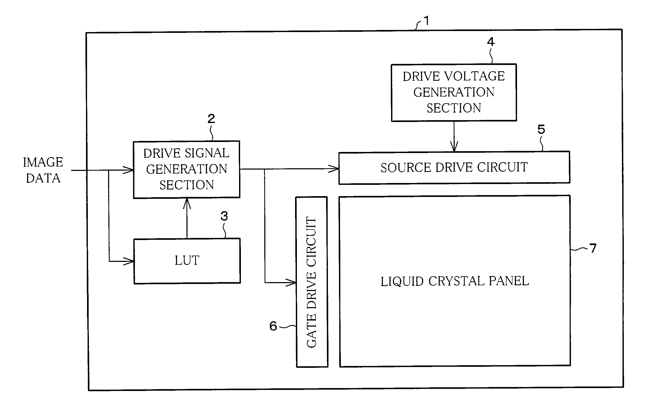
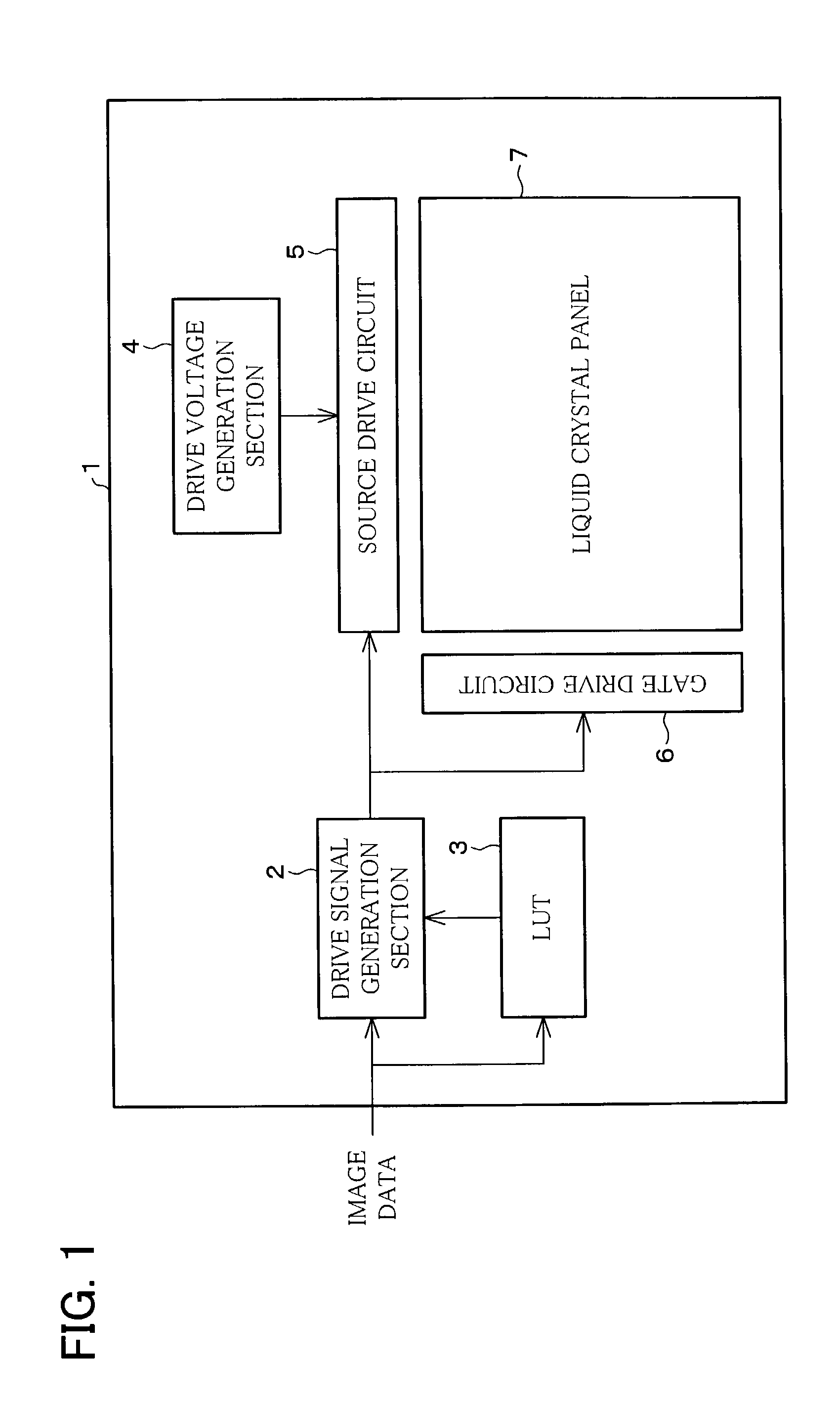
[0095]As shown in FIG. 1, a liquid crystal display device 1 as a display device according to the present embodiment has an active matrix type arrangement, including a drive signal generation section 2, an LUT (Look-Up Table) 3, a drive voltage generation section 4, a source drive circuit 5, a gate drive circuit 6, a liquid crystal panel (display panel) 7.

[0096]The drive signal generation section 2 is a circuit for generating a drive signal for operating the source drive circuit 5 and the gate drive circuit 6, in accordance with image data and a reference result of the LUT 3. The generated signals are outputted to the source drive circuit 5 and the gate drive circuit 6, respectively.

[0097]The LUT 3 is a conversion table for converting image data as display data so that gradation properties can be secured in a wide viewing angle, when the image data is displayed on the liquid crystal panel 7. More specifically, the LUT 3 is supplied thereto the same data as the image...

second embodiment

[Second Embodiment]

[0165]The following will explain another embodiment of the present invention. Note that, as to a liquid crystal display device according to the present embodiment, detailed explanations are omitted here because it has substantially the same arrangement as the liquid crystal display device, which is shown in FIG. 1, described in First Embodiment.

[0166]Unlike the liquid crystal display device 1 in the above First Embodiment, the liquid crystal display device according to the present embodiment includes a liquid crystal panel 31 as shown in FIG. 12.

[0167]The liquid crystal panel 31 has an arrangement in which one pixel includes a pixel electrode of white (W), in addition to the pixel electrodes, red (R), green (G), blue (B). More specifically, as shown in FIG. 13, one pixel 32 is composed of four sub-pixels: a red sub-pixel 33, a green sub-pixel 34, a blue sub-pixel 35, and a white sub-pixel 36, and four sub-pixels are combined to display.

[0168]The sub-pixels are ind...

third embodiment

[Third Embodiment]

[0192]The following will explain still another embodiment of the present invention. Note that, members having the same functions as those described in the foregoing embodiments are given the same reference numerals and explanations thereof are omitted here.

[0193]As shown in FIG. 14, the liquid crystal display device 41 according to the present embodiment has the same arrangement as that of the liquid crystal display device 1 shown in FIG. 1 of First Embodiment. More specifically, the liquid crystal display device 41 includes a drive signal generation section 42, an LUT 43, a drive voltage generation section 44, a source drive circuit 45, a gate drive circuit 46, a liquid crystal panel 47; and has a further arrangement in which image data is supplied via a video board 48 to the drive signal generation section 42. The video board 48 is a board for digitalizing image data.

[0194]Note that, as to the liquid crystal display device 41, detailed explanations are omitted he...


PUM

PropertyMeasurementUnit
frequenciesaaaaaaaaaa
θaaaaaaaaaa
luminance ratioaaaaaaaaaa

Abstract

A liquid crystal display device including a liquid crystal panel being capable of gradation display is provided with a LUT and a drive signal generation section for adjusting gradation curve's distortion with respect to a viewing angle, which indicates a relation between a gradation and a luminance ratio on a display screen of the liquid crystal panel. With this arrangement, it is possible to freely switch on the display screen of the liquid crystal panel between a wide viewing angle display and a narrow viewing angle display. Therefore, it is possible to provide a liquid crystal display device which adjusts the gradation curve's distortion with respect to the viewing angle on the display screen to obtain a high contrast and an excellent gradation curve in a wide range of viewing angle, thereby improving a display quality level of a display screen; and which realizes a display screen with a narrow viewing angle, thereby allowing information not desired to be seen by other people to be securely displayed thereon.

Description

FIELD OF THE INVENTION[0001]The present invention relates to a liquid crystal display device being capable of gradation display.BACKGROUND OF THE INVENTION[0002]Generally, an active matrix type liquid crystal display device has a structure of a pair of glass substrates opposed and fixed which between a liquid crystal is filled in a space. More specifically, transparent common electrodes are provided on one glass substrate, a large number of transparent pixel electrodes are provided in a matrix manner on the other glass substrate, and a circuit for individualistically applying voltages to the pixel electrodes.[0003]The liquid crystal display device performs display operation with sandwiched polarizing plates in the foregoing structure, so that it has a characteristic of a narrow viewing angle.[0004]To increase a viewing angle, have been proposed liquid crystal display devices utilizing IPS (In Plane Switching), MVA (Multi domain Vertical Aline), or ASV (Advance Super View) mode as a ...

Claims


Application Information

Patent Timeline
Patent Type & Authority Patents(United States)
IPC IPC(8): G09G3/36G09G3/34G09G5/10G02F1/133G09G3/20
CPCG09G3/3614G09G3/3648G09G3/2022G09G3/3607G09G2300/0443G09G2300/0447G09G2340/06G09G2320/0276G09G2320/028G09G2320/0606G09G2320/0673G09G2320/068G09G2300/0452G02F1/133
Inventor SAWABE, DAIICHI
Owner SHARP KK
Why Eureka
Try Eureka