Flow cytometer for differentiating small particles in suspension

Active Publication Date: 2006-09-26
BECKMAN COULTER INC
View PDF5 Cites 115 Cited by
  • Summary
  • Abstract
  • Description
  • Claims
  • Application Information

AI Technical Summary

Benefits of technology

[0009]In accordance with one aspect of the invention, it is recognized that the output beam from a laser diode is plane-polarized in the plane in which the beam is diverging the fastest. Further, it is recognized that measurement of side-scattered radiation in a flow cytometer requires that the plane of polarization of the irradiating laser beam must be parallel to the direction of the particle path through the flow cell. Still further, it is recognized that in a flow cytometer of the type described above, i.e., one i

Problems solved by technology

For example, in addition to being relatively low-power devices, laser diodes typically emit non-collimated radiation that must be collimated for practical use.
While this collimating lens readily collects all of the energy diverging from the source at the smaller angle, it often truncates a portion of the beam diverging at the larger angle.
While these spurious light sources are usually of relatively low intensity compared to the collimated main beam, they can be problematic to the performance of a flow cytometer.
But, as noted by Ozasa et al., a significant drawback of this conventional orientation of a laser diode in a flow cytometer is that it acts to position the above-noted light-lobes directly in the particle path, causing the detectors to

Method used


Image

  • Flow cytometer for differentiating small particles in suspension
  • Flow cytometer for differentiating small particles in suspension
  • Flow cytometer for differentiating small particles in suspension

Examples


Embodiment Construction

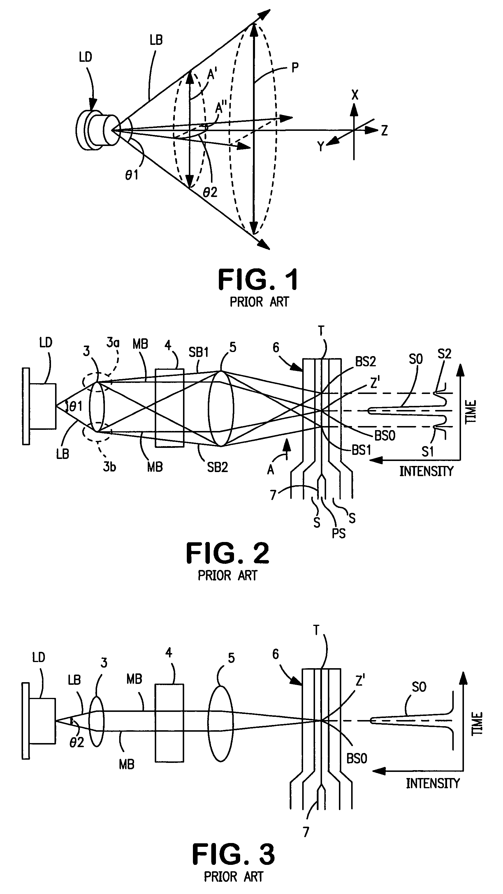
[0016]Referring now to the drawings, FIG. 1 schematically illustrates a conventional laser diode LD of the type that emits a diverging laser beam LB having an elliptical cross-section that expands in size in accordance with two different angles of divergence, θ1 and θ2. As illustrated, these angles are measured in mutually perpendicular planes, and one angle, in this case angle θ1, is usually substantially larger than the other. As is characteristic of laser diodes, the emitted laser beam LB will be plane-polarized in a plane P that is parallel to the major axis A′ of the expanding elliptical cross-section of the beam. The minor axis A″ of the elliptical cross-section is, of course, perpendicular to the major axis A′.

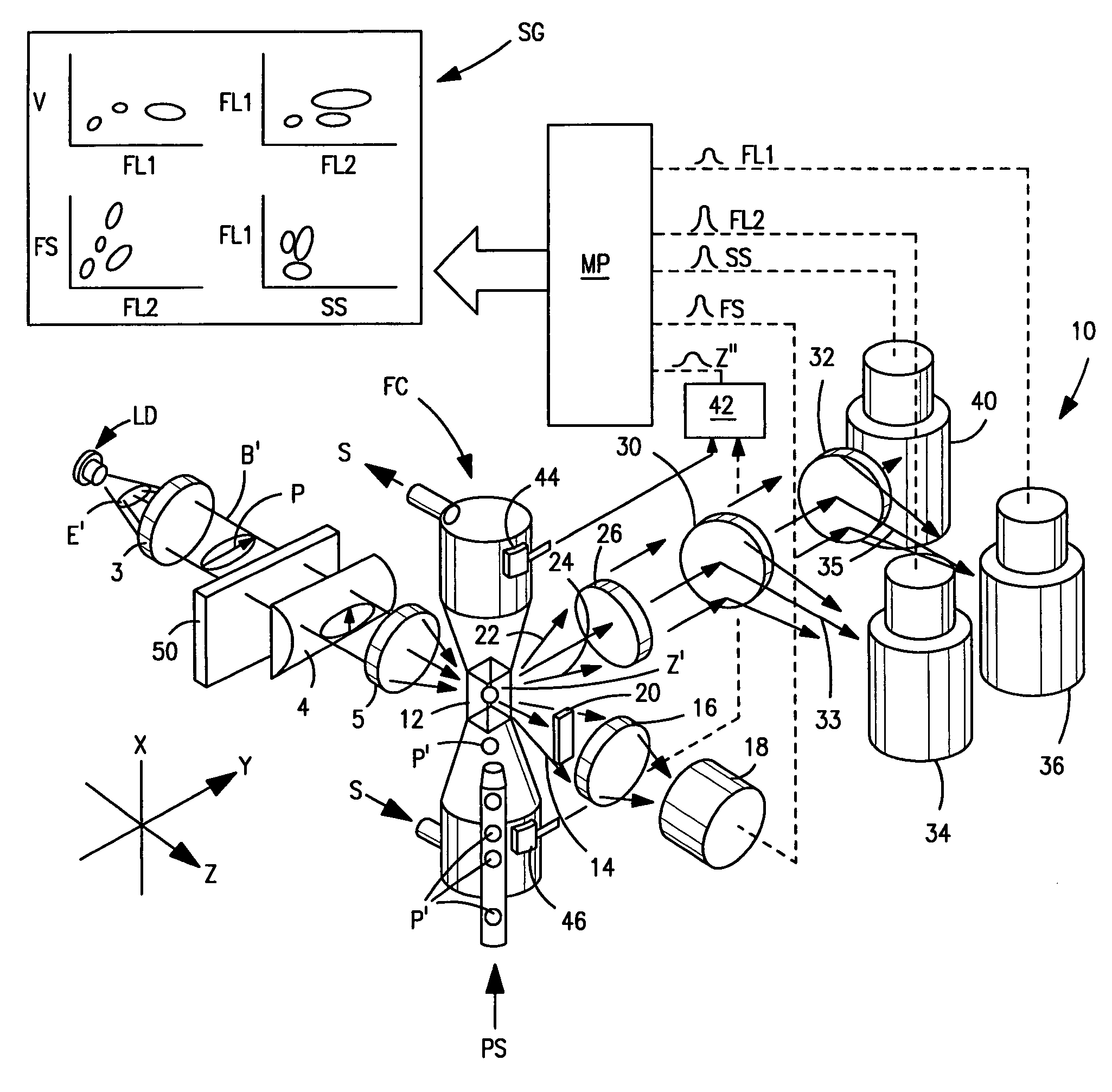
[0017]In FIG. 2, the laser diode LD of FIG. 1 is shown as being embodied in a flow cytometer of the earlier type described above. A particle sample PS containing particles to be analyzed, e.g., blood cells, is introduced by a nozzle 7 into an optically-transparent flow ...


PUM


Abstract

A flow cytometer includes an optical flow cell through which particles to be characterized on the basis of at least their respective side-scatter characteristics are caused to flow seriatim. A plane-polarized laser beam produced by a laser diode is used to irradiate the particles as they pass through a focused elliptical spot having its minor axis oriented parallel to the particle flow path. Initially, the plane of polarization of the laser beam extends perpendicular to the path of particles through the flow cell. A half-wave plate or the like is positioned in the laser beam path to rotate the plane of polarization of the laser beam so that it is aligned with the path of particles before it irradiated particles moving along such path.

Description

BACKGROUND OF THE INVENTION[0001]1. Field of the Invention[0002]The present invention relates to improvements in flow cytometers of the type commonly used to differentiate small particles, e.g., various types of blood cells, in a liquid suspension. More particularly, this invention relates to improvements in flow cytometers of the type that use plane-polarized radiation, e.g., that emitted from laser diodes, to irradiate individual particles passing through an optical flow cell in order to detect the light-scattering characteristics of such particles and thereby characterize each particle as being a member of a particular class or type.[0003]2. The Prior Art[0004]Flow cytometers are commonly used to differentiate individual small particles of different types in a particle suspension on the basis of the light-scattering and / or fluorescence characteristics of each particle. Such instruments generally include an optically-transparent flow cell having a particle-interrogation zone throu...

Claims


Application Information

Patent Timeline
IPC IPC(8): G01N21/00G01N15/02
CPCG01N15/1404G01N15/1434
Inventor WELLS, MARK A.
Owner BECKMAN COULTER INC
Why Eureka
Try Eureka