
Integrated power modules with a cooling passageway and methods for forming the same

a technology of integrated power modules and cooling passages, which is applied in the direction of cooling/ventilation/heating modifications, lighting and heating apparatus, and support structure mounting, etc., can solve the problems of large enclosures, difficult to mount the inductor on the pcb including the other circuit components, and difficult to mount the inductor on the pcb

Active Publication Date: 2006-09-26
EATON INTELLIGENT POWER LTD
View PDF5 Cites 41 Cited by
  • Summary
  • Abstract
  • Description
  • Claims
  • Application Information

AI Technical Summary

Benefits of technology

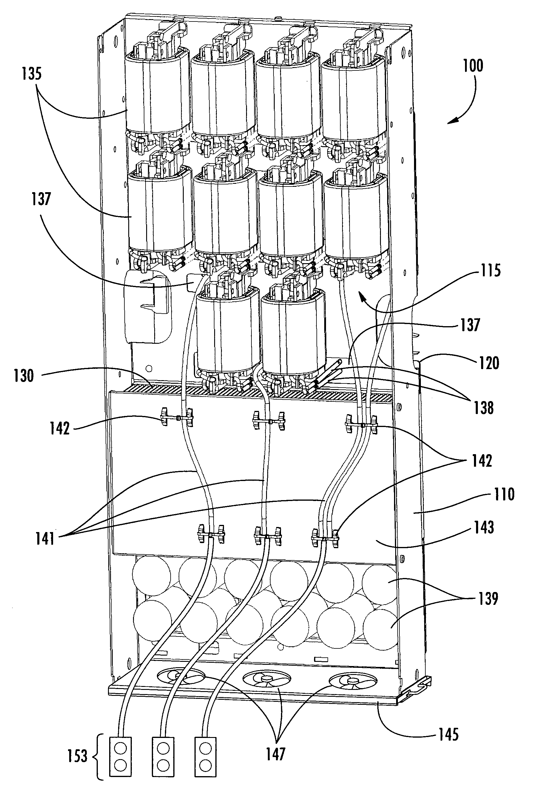
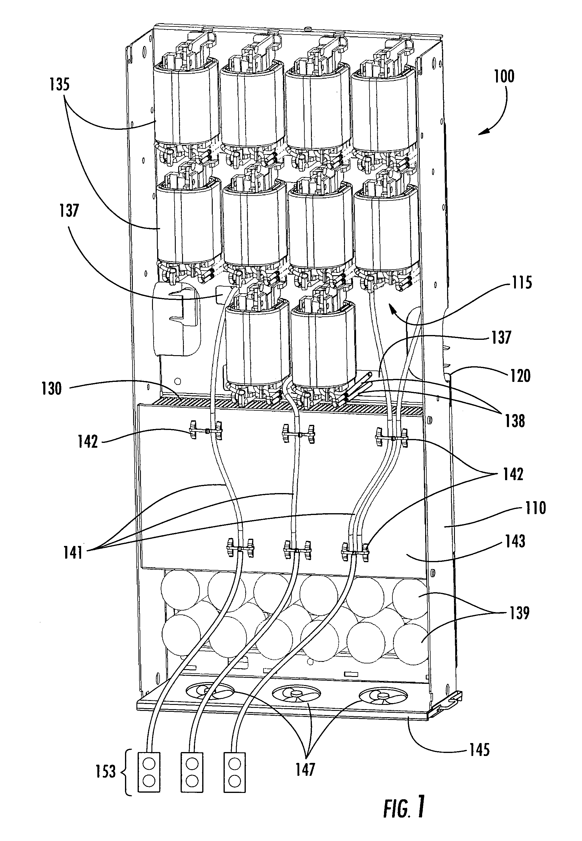
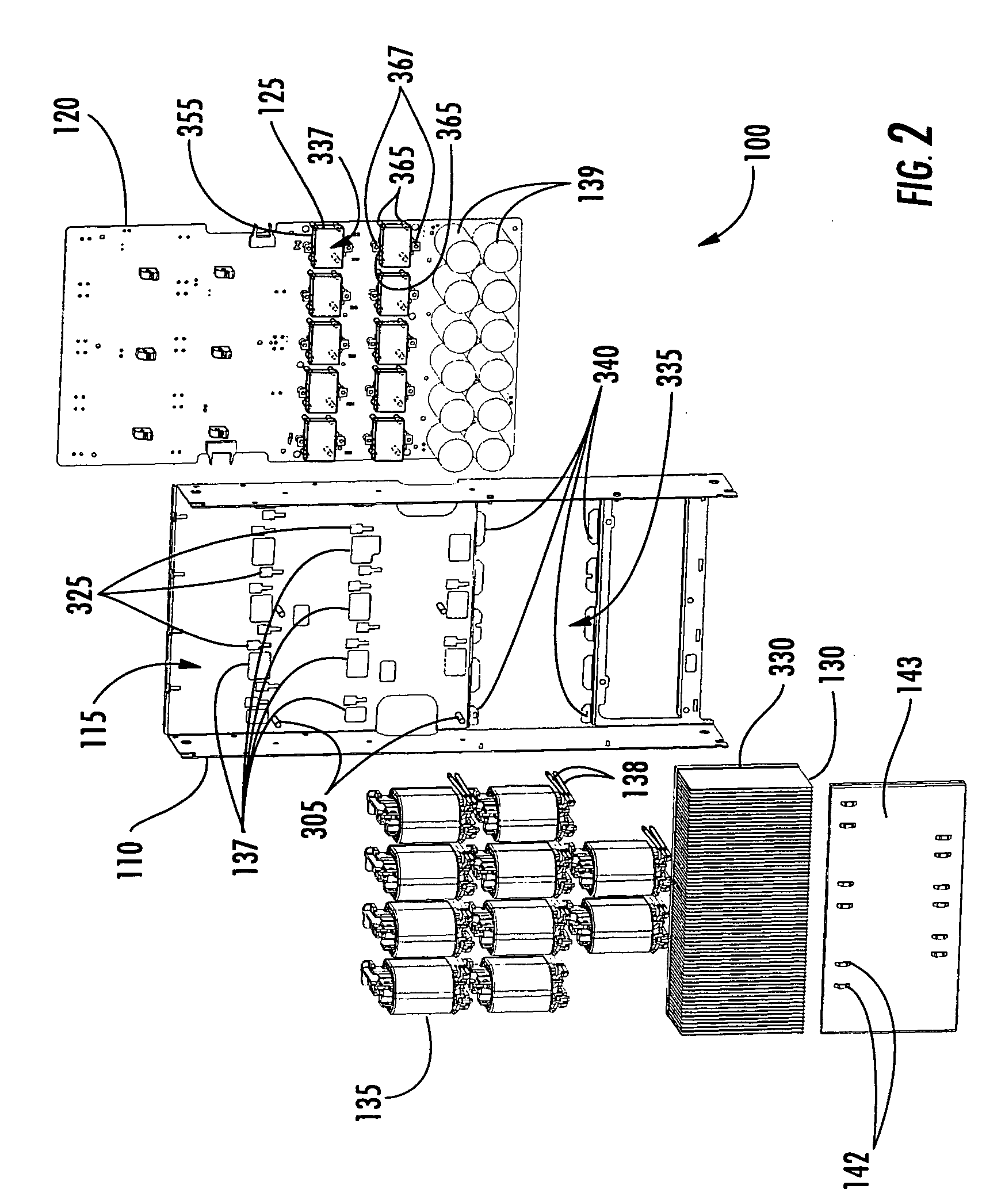
The present invention provides integrated power modules with a cooling passageway and a heat generating power circuit positioned on a printed circuit board. A heat sink is positioned in the cooling passageway on a mounting member. The power module also includes a power switching circuit and an inductor. The mounting member has mounting posts for mounting the printed circuit board. The invention also includes a registration member with a first and second tab for positioning the printed circuit board relative to the heat sink. The power module may also include a mounting arm for connecting the heat generating power circuit to the heat sink. The invention also provides a power converter apparatus with a housing containing a pair of power modules. The method of forming an integrated power module includes installing a heat sink in a cooling passageway on a mounting member and aligning an alignment opening in the printed circuit board with a registration member of the mounting member. The invention provides more efficient and compact power modules with improved cooling and reduced space requirements.

Problems solved by technology

As such, it may be difficult to mount the inductor on the PCB including the other circuit components.
Such an arrangement typically results in the use of relatively large enclosures for the power conversion circuits.

Method used


Image

  • Integrated power modules with a cooling passageway and methods for forming the same
  • Integrated power modules with a cooling passageway and methods for forming the same
  • Integrated power modules with a cooling passageway and methods for forming the same

Examples


Embodiment Construction

[0029]Specific exemplary embodiments of the invention now will be described with reference to the accompanying drawings. This invention may, however, be embodied in many different forms and should not be construed as limited to the embodiments set forth herein; rather, these embodiments are provided so that this disclosure will be thorough and complete, and will fully convey the scope of the invention to those skilled in the art. In the drawings, the relative sizes of regions or features may be exaggerated for clarity. It will be understood that when an element is referred to as being “connected” or “coupled” to another element, it can be directly connected or coupled to the other element or intervening elements may be present. As used herein the term “and / or” includes any and all combinations of one or more of the associated listed items. Like numbers refer to like elements throughout.

[0030]Embodiments of the present invention will now be described with reference to the various emb...


PUM


Abstract

An integrated power module includes a longitudinally extending mounting member defining a cooling passageway on a first side thereof. A heat sink is positioned in the cooling passageway. A printed circuit board is positioned proximate a second side of the mounting member opposite the first side. A heat generating power circuit is electrically coupled to the printed circuit board and positioned between the printed circuit board and the mounting member. The power circuit is thermally coupled to the heat sink. An inductor is mounted in the cooling passageway. Methods of forming an integrated power module are also provided.

Description

BACKGROUND OF THE INVENTION[0001]The present invention relates to power modules and, more particularly, to integrated power modules and method for forming the same.[0002]A power conversion device, such as a three phase uninterruptible power supply (UPS), may include multiple power conversion circuits. For example, an online UPS may include a rectifier that is used to rectify an input AC voltage to generate a DC voltage and an inverter that generates an AC voltage from this DC voltage. The UPS may also include additional power conversion circuits, such as battery charger and / or converter circuits.[0003]Such power conversion circuits typically include a variety of printed circuit board (PCB) mounted components such as inductors, current sensors insulated gate bipolar transistor (IGBT) bridge circuits. Packaged multi-transistor devices have been developed for such applications. For example, “six pack” devices are offered that include three IGBT half-bridges mounted on a common heat sin...

Claims


Application Information

Patent Timeline
Patent Type & Authority Patents(United States)
IPC IPC(8): H05K7/20H05K7/14
CPCH05K7/20909H02M7/003
Inventor ARMSTRONG, JOHNLYNAM, LARRYZENG, WINSTON L.
Owner EATON INTELLIGENT POWER LTD
Learn More