Latency evaluation in a ring network

a ring network and latency evaluation technology, applied in the field of network communication systems and protocols, can solve the problems of costly hardware typically being added to the network, the network does not provide a means for measuring round-trip, node-to-node latency between a pair of nodes on the ring,

Active Publication Date: 2006-09-26
CORRIGENT CORP
View PDF5 Cites 34 Cited by
  • Summary
  • Abstract
  • Description
  • Claims
  • Application Information

AI Technical Summary

Benefits of technology

[0012]It is an object of the present invention to provide improved methods

Problems solved by technology

The methods described by Grow et al. can be used for measuring latency of transmission around the entire ring in a single direction, but they do not provide a means for measuring round-trip, node-to-node latency between a pair of nodes on the ring.
These methods suffer from the drawback that the measured latency includes the time taken by the destination node to process th

Method used


Image

  • Latency evaluation in a ring network
  • Latency evaluation in a ring network
  • Latency evaluation in a ring network

Examples


Embodiment Construction

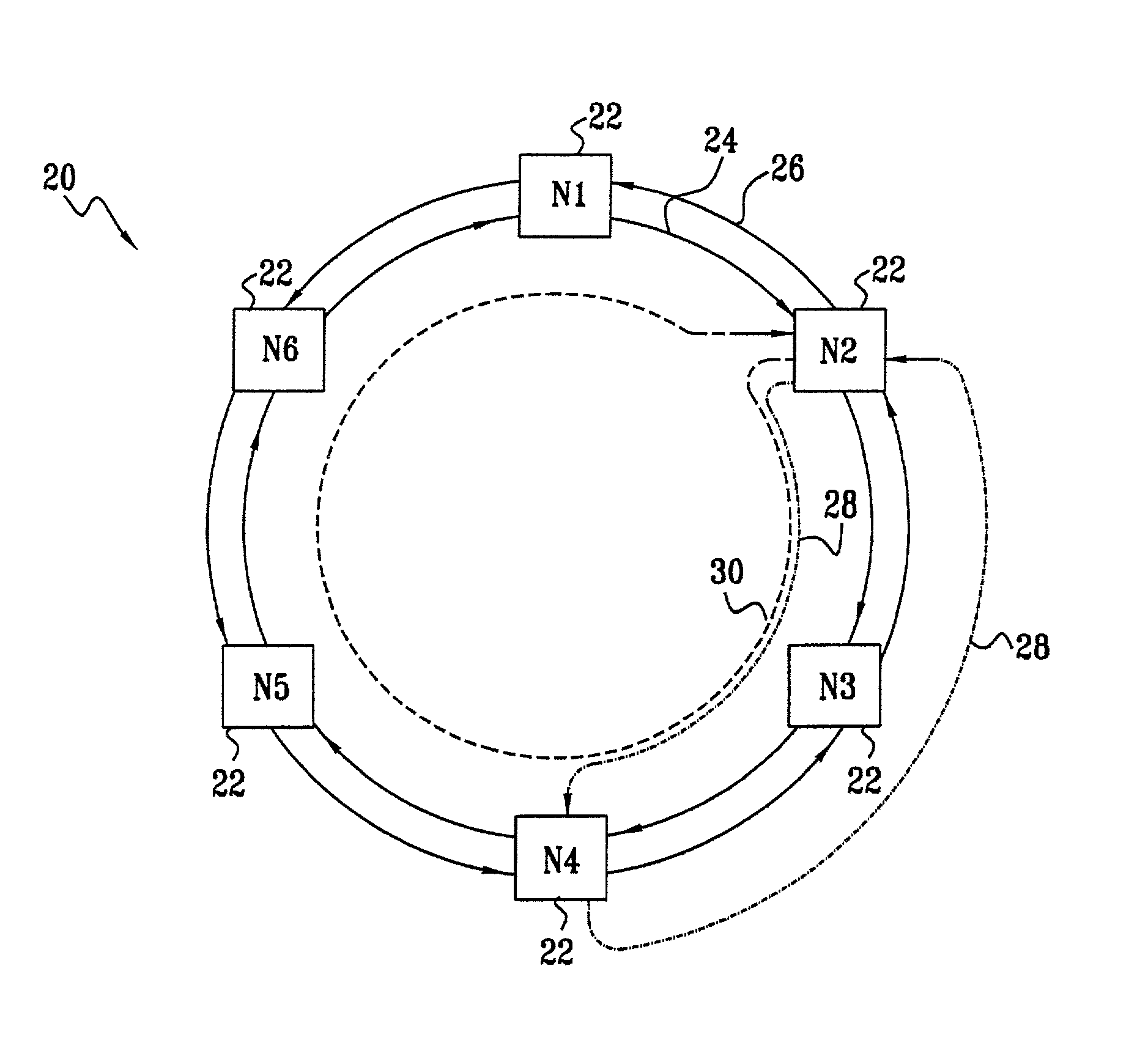
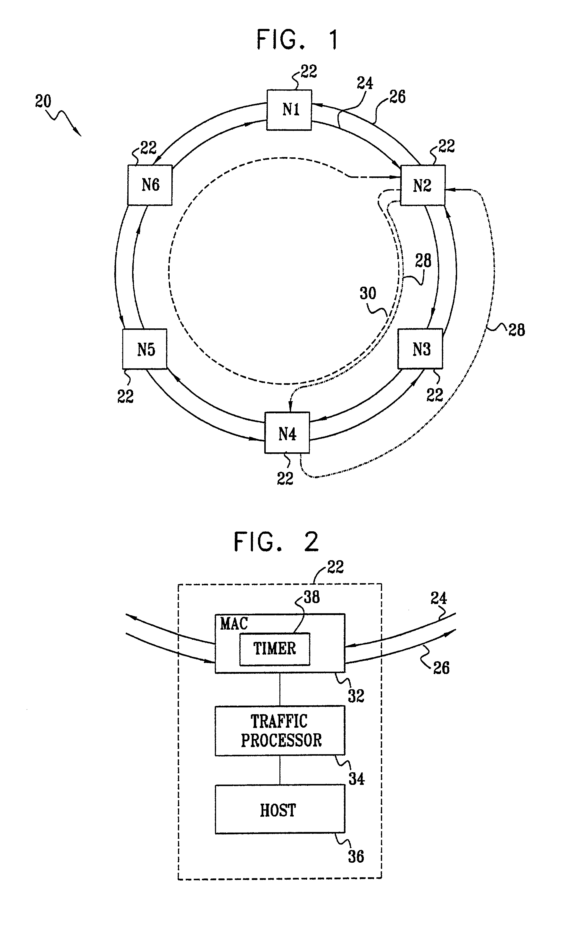
[0051]FIG. 1 is a block diagram that schematically shows a packet ring network 20, in accordance with a preferred embodiment of the present invention. Network 20 comprises nodes 22, marked N1 through N6, which are mutually connected by bidirectional communication media, such as optical fibers or conductive wires. The nodes typically comprise switching equipment, and serve as either access points or gateways to other networks (aggregation points). The communication media in network 22 are configured to define an inner ring 24, over which packets are conveyed between the nodes in a clockwise direction, and an outer ring 26, over which the packets are conveyed in a counterclockwise direction. As noted above, however, the designations of “inner,”“outer,”“clockwise” and “counterclockwise” are arbitrary and are used here simply for convenience and clarity of explanation. Furthermore, the designation and number of nodes in network 20 are chosen here by way of example, and the network may, ...


PUM


Abstract

A method for measuring latency in a bi-directional ring network includes transmitting a latency measurement packet from an originating node to a peer node and noting a time of receipt of the packet at the peer node. The packet is then transmitted back to the originating node in the opposite direction, while recording in the packet an indication of a peer node difference between a time of transmission of the packet from the peer node to the originating node and the time of receipt of the packet at the peer node. A time of return of the packet to the originating node is noted, so as to determine an originating node difference between a time of transmission of the packet from the originating node to the peer node and the time of return of the packet to the originating node. The latency is calculated by taking a difference between the originating node difference and the peer node difference.

Description

FIELD OF THE INVENTION[0001]The present invention relates generally to network communication systems and protocols, and specifically to methods of latency measurement in packet-switched networks, and particularly in ring networks.BACKGROUND OF THE INVENTION[0002]Network ring topologies are gaining in popularity, particularly in Internet Protocol (IP) networks. Such networks enable carriers to offer large bandwidth to users in a cost-effective manner, since each node in the network needs only two interfaces, rather than having to maintain a separate interface for each of the other nodes as in a mesh network.[0003]Recently-developed bidirectional protocols provide efficient bandwidth utilization by enabling data to be transferred between any pair of nodes in either direction around the ring, while maintaining fast protection against faults. The two opposing traffic directions are commonly referred to as an inner ring and an outer ring. It will be understood, however, that in the conte...

Claims


Application Information

Patent Timeline
IPC IPC(8): G01R31/08H04L12/24H04L12/26
CPCH04L12/2697H04L12/427H04L43/50H04L43/0858H04L43/0864H04L41/5022
Inventor BRUCKMAN, LEON
Owner CORRIGENT CORP
Why Eureka
Try Eureka