
Method for software driven generation of multiple simultaneous high speed pulse width modulated signals

a technology of pulse width and modulation signal, which is applied in the direction of pulse characteristics, pulse techniques, instruments, etc., can solve the problems of not cost effective to dedicate a data processing platform to the task of running timer modules for a pwm application, affecting the resolution of pwm signals, and affecting the accuracy of pwm signals

Inactive Publication Date: 2006-09-26
PHILIPS SOLID STATE LIGHTING SOLUTIONS
View PDF126 Cites 272 Cited by
  • Summary
  • Abstract
  • Description
  • Claims
  • Application Information

AI Technical Summary

Benefits of technology

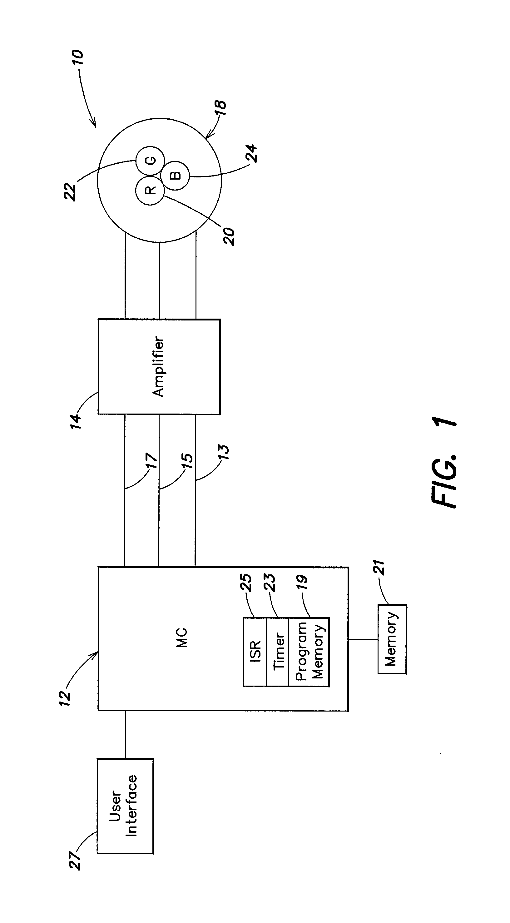
[0024]In one practice, the systems and methods described herein provide control systems that allow for the modulation of a lamp that includes a red, green, and blue component. Each color component of the lamp can be associated with a particular channel. Ea

Problems solved by technology

However, although these systems can work quite well, it is often not cost effective to dedicate a data processing platform to the task of running timer modules for a PWM application.
Thus, the time period for executing the update instructions can be significant, and the PWM signal may have poor resolution, lacking fine grain control over the system.
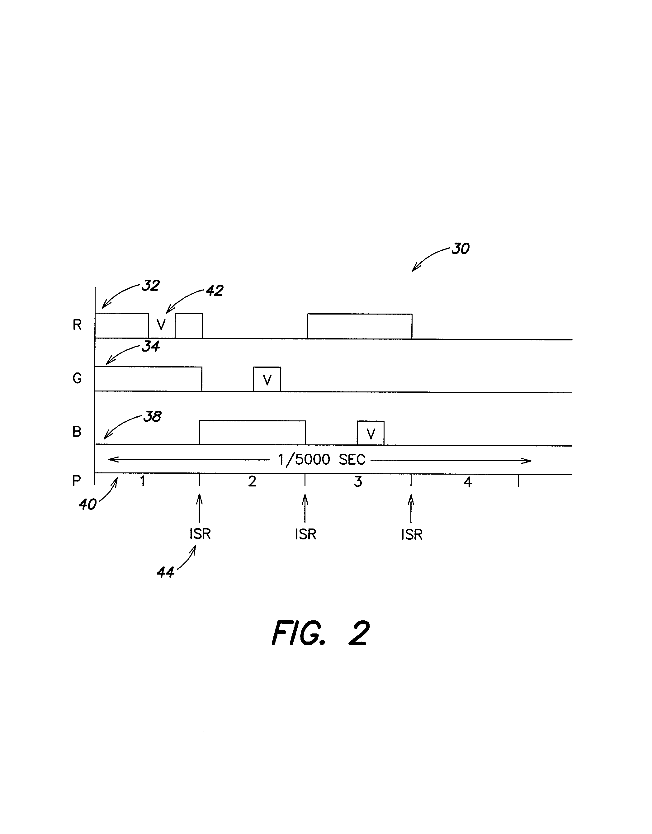
The difficulty with this method is that for multiple PWM channels it is very difficult to arrange the timer based signal updates such that they do not overlap, and then to accurately change the update times for a new value of PWM signals.

Method used


Image

  • Method for software driven generation of multiple simultaneous high speed pulse width modulated signals
  • Method for software driven generation of multiple simultaneous high speed pulse width modulated signals
  • Method for software driven generation of multiple simultaneous high speed pulse width modulated signals

Examples


Embodiment Construction

[0030]The invention will now be set forth with reference to certain illustrated embodiments, including control systems that allow for the modulation of the hue of colored light generated by a lamp having a red, green and blue component. However, it will be understood by those of ordinary skill in the art that these illustrated embodiments are merely representative of the systems and methods that are provided by the invention and that other embodiments can be realized without departing from the scope of the invention. For example, the systems and methods described herein can further be employed for providing PWM control systems suitable for controlling the operation of a motor, including controlling the speed at which the motor rotates. Further, it will be understood that the systems and methods described herein can be employed for controlling the power delivered to an electronic device, including a traditional incandescent lightbulb, for controlling the brightness at which the light...


PUM


Abstract

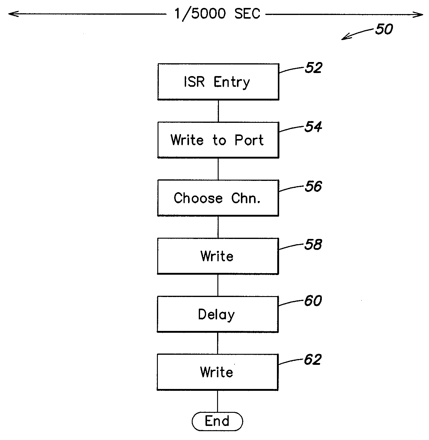
Systems and methods can provide, in one aspect, a method for modulating the pulse width of control signals generated on a plurality of separate channels. In one practice, the methods described herein are suitable for execution on a microprocessor or micro controller platform that includes a timer interrupt mechanism which will generate an interrupt in response to a timer counting down a selected time interval or time period. In one practice, the timer is set to count down a period of time that is representative of a portion, or sub period, of the PWM cycle. Upon expiration of that time period, the timer executes an interrupt that causes the micro controller to enter an interrupt service routine (ISR) that can further modulate the PWM cycle of one or more signals.

Description

CROSS-REFERENCE TO RELATED APPLICATIONS[0001]This application claims the benefit under 35 U.S.C. §119(e) of U.S. Provisional Application Ser. No. 60 / 090,920, filed Jun. 26, 1998, and entitled Methods for Software Driven Generation of Multiple Simultaneous High Speed Pulse Width Modulated Signals. [0002]This application also is a continuation-in-part (CIP) under 35 U.S.C. §120 of, and hence claims priority to and incorporates by reference, U.S. Ser. No. 08 / 920,156, entitled Multicolored LED Lighting Method and Apparatus, U.S. patent application, filed Aug. 26, 1997, naming George Mueller and Ihor Lys as inventors, now U.S. Pat. No. 6.016,038.[0003]This application also is a continuation-in-part (CIP) under 35 U.S.C. §120 of, and hence claims priority to and incorporates by reference, U.S. patent application Ser. No. 09 / 215,624 filed on Dec. 17, 1998, now U.S. Pat. No. 6,528,954, which in turn claims the benefit of the following U.S. Provisional Applications:[0004]Ser. No. 60 / 071,281,...

Claims


Application Information

Patent Timeline
IPC IPC(8): H03K7/08
CPCH05B33/0818H05B33/086H05B37/029H05B33/0863Y02B20/346H05B45/20H05B45/325H05B47/155Y02B20/30
Inventor LYS, IHOR A.MORGAN, FREDERICK M.
Owner PHILIPS SOLID STATE LIGHTING SOLUTIONS
Learn More