
Packet retransmission system, packet transmission device, packet reception device, packet retransmission method, packet transmission method and packet reception method

a packet retransmission and packet technology, applied in digital transmission, data switching networks, instruments, etc., can solve the problems of often lost packets in networks and performing useless retransmission processing

Inactive Publication Date: 2006-09-26
MITSUBISHI ELECTRIC CORP
View PDF13 Cites 97 Cited by
  • Summary
  • Abstract
  • Description
  • Claims
  • Application Information

AI Technical Summary

Benefits of technology

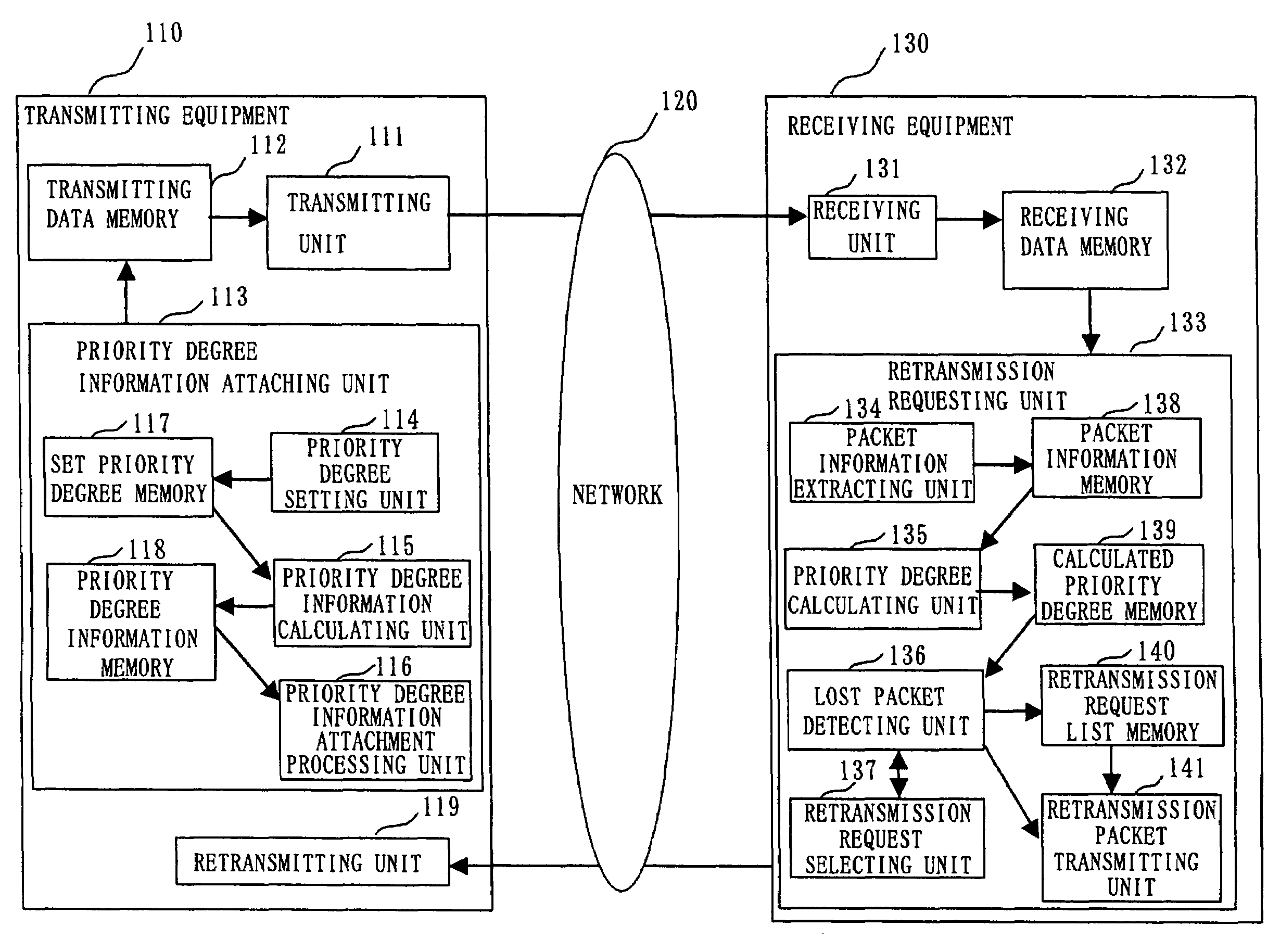
[0019]The priority degree setting unit selects a priority degree one by one from a higher order among the plurality of priority degrees, judges an importance degree of data included in the packet based on the priority degree selected, and increases a value of the priority degree selected by one and sets the value of the priority degree selected when it is judged as an important packet.

Problems solved by technology

Generally, a packet transmitted in a network is often lost due to an overflow at a node (router) provided in the network, bit error in a wireless space, etc.
Further, an excess of the ACK packet and an increase of the retransmission packet pressure a band, and cause congestion.
Further, the receiver waits for the retransmission packet and requests the retransmission many times. The receiver is performing a useless retransmission processing.

Method used


Image

  • Packet retransmission system, packet transmission device, packet reception device, packet retransmission method, packet transmission method and packet reception method
  • Packet retransmission system, packet transmission device, packet reception device, packet retransmission method, packet transmission method and packet reception method
  • Packet retransmission system, packet transmission device, packet reception device, packet retransmission method, packet transmission method and packet reception method

Examples


embodiment 1

[0110]In this embodiment, an example in case of PH=2 is explained.

[0111]FIG. 4 shows a flow chart of an example of the operations by the transmitter in Embodiment 1. FIG. 5 shows a flow chart of an example of the operations by the receiver in Embodiment 1.

[0112]This shows a sequence of a packet which is being processed among packets to be sent.

[0113]The transmitter calculates PLDi (PLD of the i-th packet) from the packet with i=0, and transmits the packet. At first, when the transmitter receives the retransmission request packet (Yes in 603), the retransmitting unit 119 retransmits the packet of which retransmission is requested (604). In the retransmission request packet, PL of each of priority degrees, which is desired to be retransmitted, is written. For example, information of requesting a packet with PL(0)=5, 6 and PL(1)=4 is written in the retransmission request packet. The retransmission request packet can be in any configuration as far as the PL for requesting the retransmis...

embodiment 2

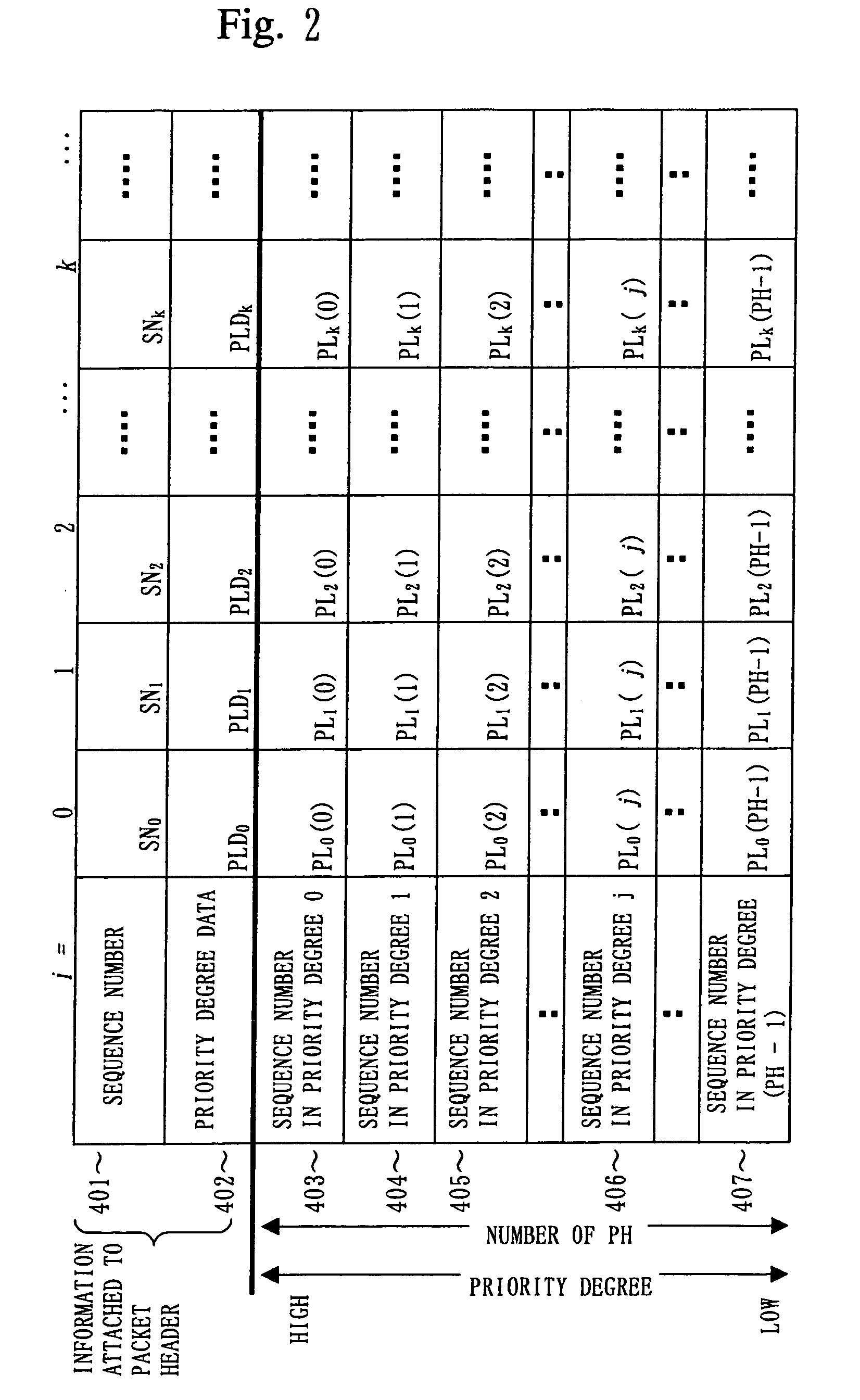
[0143]In Embodiment 2, a case of calculating the priority degree data so that the value of the PLD becomes smaller than Embodiment 1 is explained.

[0144]In the receiver, the priority degree data PLD are treated as PLD=SN×Q+R. Q is a quotient of PLD / SN, and R is a remainder of 3. Values of Q and R are also set smaller for each of the packets.

[0145]In the following explanation, explanations are made by using an equation of PLD=SN×Q+R.

[0146]At first, setting of the value of Q is explained. Variables A, B and C calculated in the following equation are defined.

[0147]A=|PLD(N−1)−PL(N)|, B=|SN−PLD(N−1)|, C=|SN−PL(N)|, and a minimum value among A, B and C is defined as Q. Further, an identifier PQ for identifying which value among three values is defined as Q, and displayed in 2 bits for example.

[0148]In case of Q=PL(0), i.e., same as Embodiment 1, PQ=00.

[0149]In case of Q=A, PQ=01.

[0150]In case of Q=B, PQ=10.

[0151]In case of Q=C, PQ=11.

[0152]Further, since A, B and C are absolute values of ...

embodiment 3

[0196]In Embodiments 1 and 2, a case of PH=2 was explained as an example. However, even when PH is larger than 2, this packet retransmitting system can be applied.

[0197]For example, in FIG. 7, PL is specified in case of PH=1≠2. However, for specifying the PL in case of PH=3≠4, another row of format data of a last line is added. In case of PH=5≠6, another row is further added. Information on the PL for requesting the retransmission is added.


PUM


Abstract

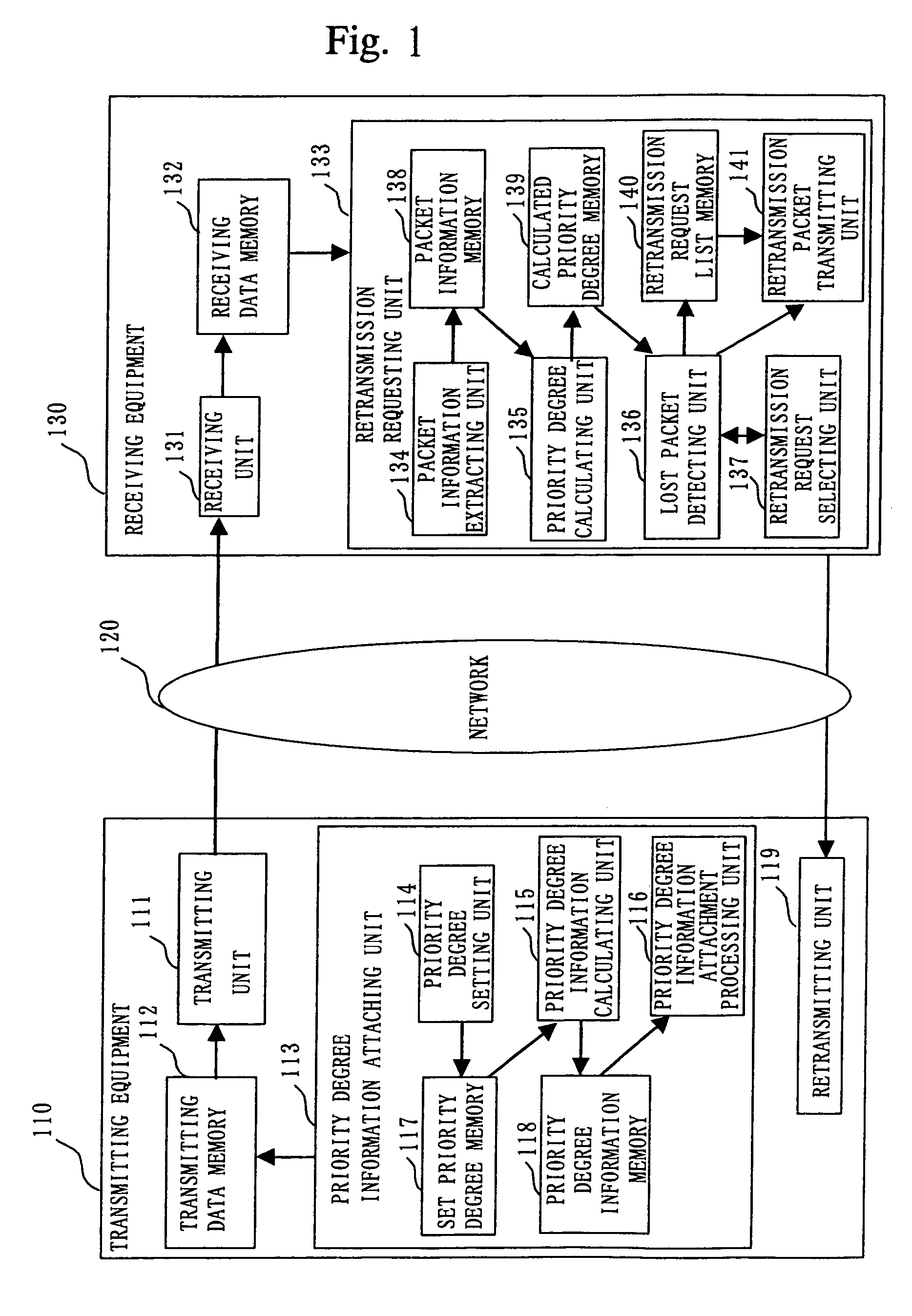
In a packet retransmitting system for retransmitting a packet including a sequence number in a packet header, which is lost during packet communication, a transmitting equipment (110) includes a priority degree information attaching unit (113) for defining a plurality of priority degrees, setting an importance degree of each of the plurality of priority degrees for a packet, producing priority degree information by using the plurality of priority degrees, and attaching the priority degree information to the packet header included in the packet repeatedly for each of the plurality of packets, a transmitter (111) for transmitting the plurality of packets, and a retransmitting unit (119) for receiving a retransmission request packet and retransmitting a packet of which retransmission is requested in the retransmission request packet received. A receiving equipment (130) includes a receiving unit (131) for receiving the plurality of packets and a retransmission requesting unit (133) for extracting a plurality of sequence numbers and a plurality of priority degree information from the packet header, detecting lost packets based on the plurality of sequence numbers and the plurality of priority degree information extracted, detecting an important packet among the lost packets, and requesting retransmission of the packet.

Description

[0001]This application is the national phase under 35 U.S.C. § 371 of PCT International Application No. PCT / JP00 / 06941 which has an International filing date of Oct. 5, 2000, which designated the United States of America.TECHNICAL FIELD[0002]This invention relates to a system and a method of requesting retransmission between a server for distributing data, e.g., multimedia data which have a plurality of priority degrees and a client based on the plurality of priority degrees when a packet is lost.BACKGROUND ART[0003]Generally, a packet transmitted in a network is often lost due to an overflow at a node (router) provided in the network, bit error in a wireless space, etc. In such a case, there is a method in which a receiver requests a transmitter to retransmit a lost packet, and the transmitter who is requested to retransmit retransmits the lost packet.[0004]For example, in a protocol of TCP (Transmission Control Protocol), the receiver transmits an ACK packet to the transmitter for...

Claims


Application Information

Patent Timeline
Patent Type & Authority Patents(United States)
IPC IPC(8): G06F15/16G06F15/00H04L12/70H04L1/16H04L1/18H04L12/851
CPCH04L1/1809H04L47/10H04L1/1887H04L1/1854H04L1/1671
Inventor OKUMURA, SEIJITAKATORI, NORIHITOFUKUDA, KAZUMA
Owner MITSUBISHI ELECTRIC CORP
Learn More