Joint type minnow

a joint type and minnow technology, applied in the field of lure for fishing, can solve the problems of unsuitability for use under a strong wind condition or against wind conditions, and the laborious disconnection of the line,

Inactive Publication Date: 2006-10-03
JACKSON
View PDF10 Cites 4 Cited by
  • Summary
  • Abstract
  • Description
  • Claims
  • Application Information

AI Technical Summary

Benefits of technology

[0007]The present invention has been implemented in view of the foregoing situation, and has an object to provide a novel joint type minnow in which mutual swing motions of a main body portion and a tail portion are regulated at a casting time, and the regulation of the mutual swing motions between the main body portion and the tail portion is released in water, so that a swim action inherent to a joint type minnow can be implemented in water.
[0009]According to this invention, when casting is carried out, the swing motion of the tail portion is regulated to reduce air resistance, whereby reduction in casting distance can be avoided.
[0011]According to the present invention, the swing motion of the tail portion is regulated to thereby reduce air resistance at the casting time, and the regulation is released in water so that the joint type minnow takes a swim action inherent thereto in water.
[0013]According to the present invention, the fixing stick is movable by its own weight, so that the regulation of the swing motion and the release of the regulation can be performed without carrying out any special operation. Therefore, the fixing stick can be located in the stick accommodating portion formed in the tail portion to regulate the swing motion of the tail portion at the time point when an angler takes a casting position and a lure falls into an erected state. When the angler starts retrieval and the lure is set in a frontward inclined position, the fixing stick can be located in the stick accommodating portion formed in the main body portion, and thus the regulation of the swing motion can be released.

Problems solved by technology

Particularly when the joint portion 10′ is tangled with the line L, it needs a lot of labor to disentangle the line L. Accordingly, the conventional joint type minnow M′ is unsuitable for use under a strong wind condition or against wind condition.

Method used


Image

  • Joint type minnow
  • Joint type minnow
  • Joint type minnow

Examples


Embodiment Construction

[0025]A preferred embodiment according to the present invention will be described hereunder with reference to the accompanying drawings. In the following description, the present invention will be described by using a preferred embodiment of a joint type minnow. However, the present invention is not limited to the following embodiment, and various technical modifications may be made to the embodiment without departing from the subject matter of the present invention.

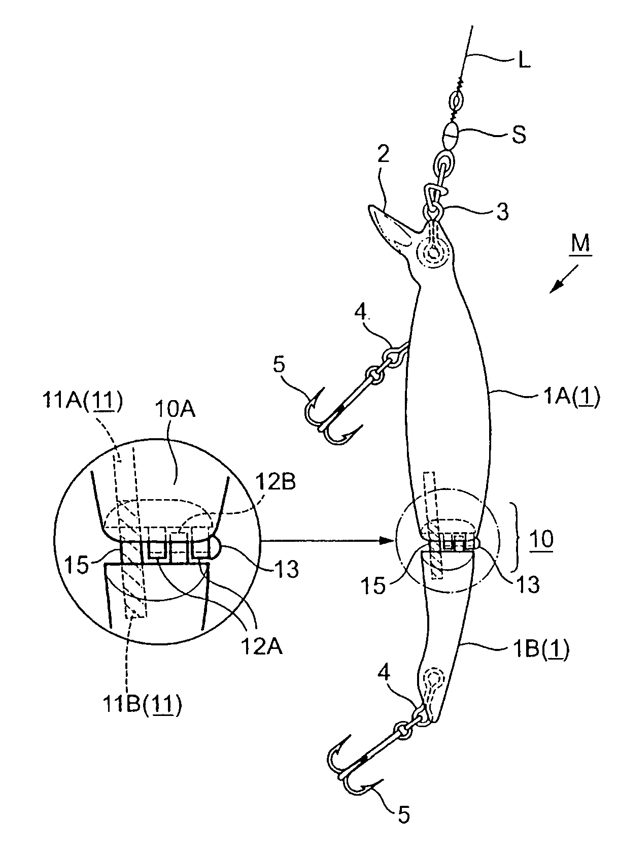
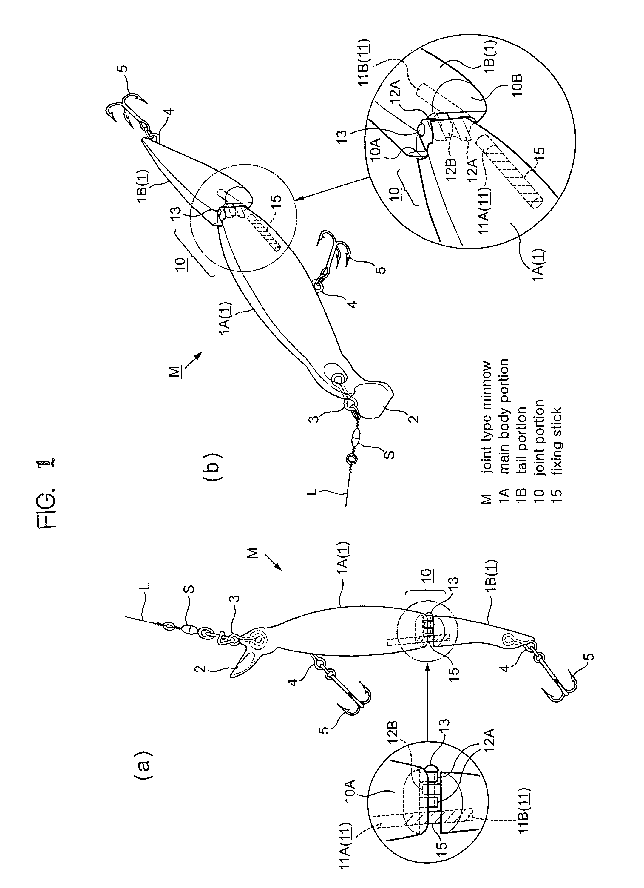
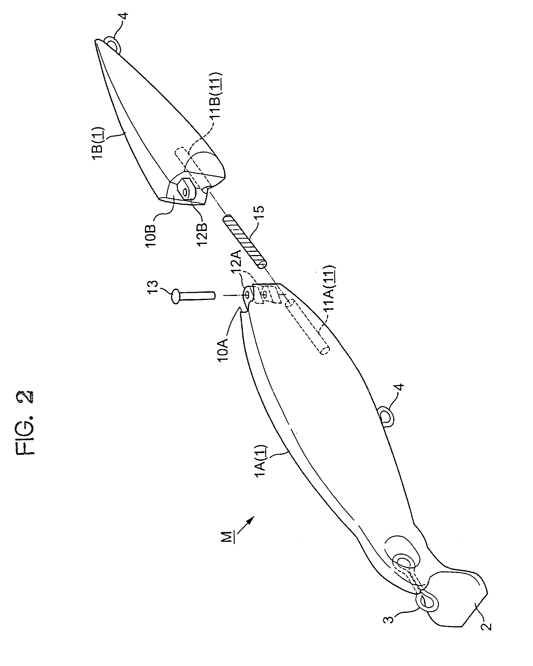
[0026]In the figures, reference character M represents a joint type minnow of the present invention, and this is a lure having a body portion 1 which is formed so as to imitate a bait fish and divided into a main body portion 1A and a tail portion 1B so as to be mutually swingably joined to each other.

[0027]A flat-plate type lip 2 is equipped in the neighborhood of a lower jaw of a head portion of the main body portion 1A, and further an annular line eye 3 is equipped to the front side of the head portion. An annular hoo...


PUM


Abstract

A joint type minnow having a body which is formed so as to imitate a bait fish and divided into a main body portion and a tail portion so that the main body portion and the tail portion are mutually swingably joined to each other through a latch structure, is further equipped with a structure for regulating the mutual swing motion between the main body portion and the tail portion. The structure regulates the swing motion of the tail portion at a casting time to reduce air resistance, thereby avoiding reduction in flight distance of the lure.

Description

BACKGROUND OF THE INVENTION[0001]1. Field of the Invention[0002]The present invention relates to a lure for fishing, and particularly to a joint type minnow which can overcome various disadvantages of conventional joint type minnows, for example, a disadvantage that a joint portion or a hook is tangled with a line, a disadvantage that a casting distance is short, etc.[0003]2. Description of the Related Art[0004]As one kind of lures supplied for bass fishing is known a so-called minnow which is formed by imitating the shape of a bait fish. Such a minnow is used while imitating motions of a bait fish such as wobbling, rolling or the like in water by drawing a line connected to a line eye equipped to the head portion of a body which mainly imitates a fish body.[0005]There is further known a so-called joint type minnow in which a body 1′ shown in FIG. 5 is divided into a main body portion 1A′ and a tail portion 1B′ and they are swingably joined to each other in order to make the motion ...

Claims


Application Information

Patent Timeline
Patent Type & Authority Patents(United States)
IPC IPC(8): A01K85/00A01K85/18
CPCA01K85/18
Inventor KATO, MASAO
Owner JACKSON
Why Eureka
Try Eureka