Angled traction lugs for endless band

a technology of lugs and endless bands, applied in the field of drive lugs, can solve the problems of high overhaul cost, limited solution, damage to the ground, etc., and achieve the effect of reducing vibration and/or noise levels

Inactive Publication Date: 2006-10-03
SOUCY INT
View PDF16 Cites 39 Cited by
  • Summary
  • Abstract
  • Description
  • Claims
  • Application Information

AI Technical Summary

Benefits of technology

[0013]4. To spread over time the meshing process of the traction lugs with the sprocket, and therefore reducing the vibration and / or noise levels caused by the meshing process.

Problems solved by technology

However, metallic tracks have drawbacks (high overhaul costs, damages to the ground, weight, noise, etc.) which led to the development of the reinforced elastomeric traction band technology.
By minimizing these drawbacks, the use of elastomeric materials for traction bands generated other problems which particularly concern the meshing of the sprocket and the traction band.
These problems include teeth skipping, detracking and they are, among other reasons, attributable to the high elasticity of elastomeric materials.
However, this solution is limited by the increased interference occurrences when a thickened drive lug meshes with its corresponding sprocket cavity.
However, these ideal conditions are rarely encountered by such vehicles equipped with elastomeric traction bands, especially since they are often subject to frequent and brutal accelerations and decelerations, and because they very often ride on inclined and irregular terrains.
These pitch variations induce important interferences and friction forces between the lug-sprocket assembly which, when combined to a tension decrease in the traction band, are sufficient to generate radial forces which can initiate de-tracking occurrences and teeth skipping.
In these conditions and for those instances, it is not possible to solve this problem by modifying the lug profile or thickening the traction lugs.
However, no prior art uses or even suggests the utilization of traction band with traction lugs configured in a chevron pattern or otherwise not parallel to the longitudinal axis of the traction band.

Method used


Image

  • Angled traction lugs for endless band
  • Angled traction lugs for endless band
  • Angled traction lugs for endless band

Examples


Embodiment Construction

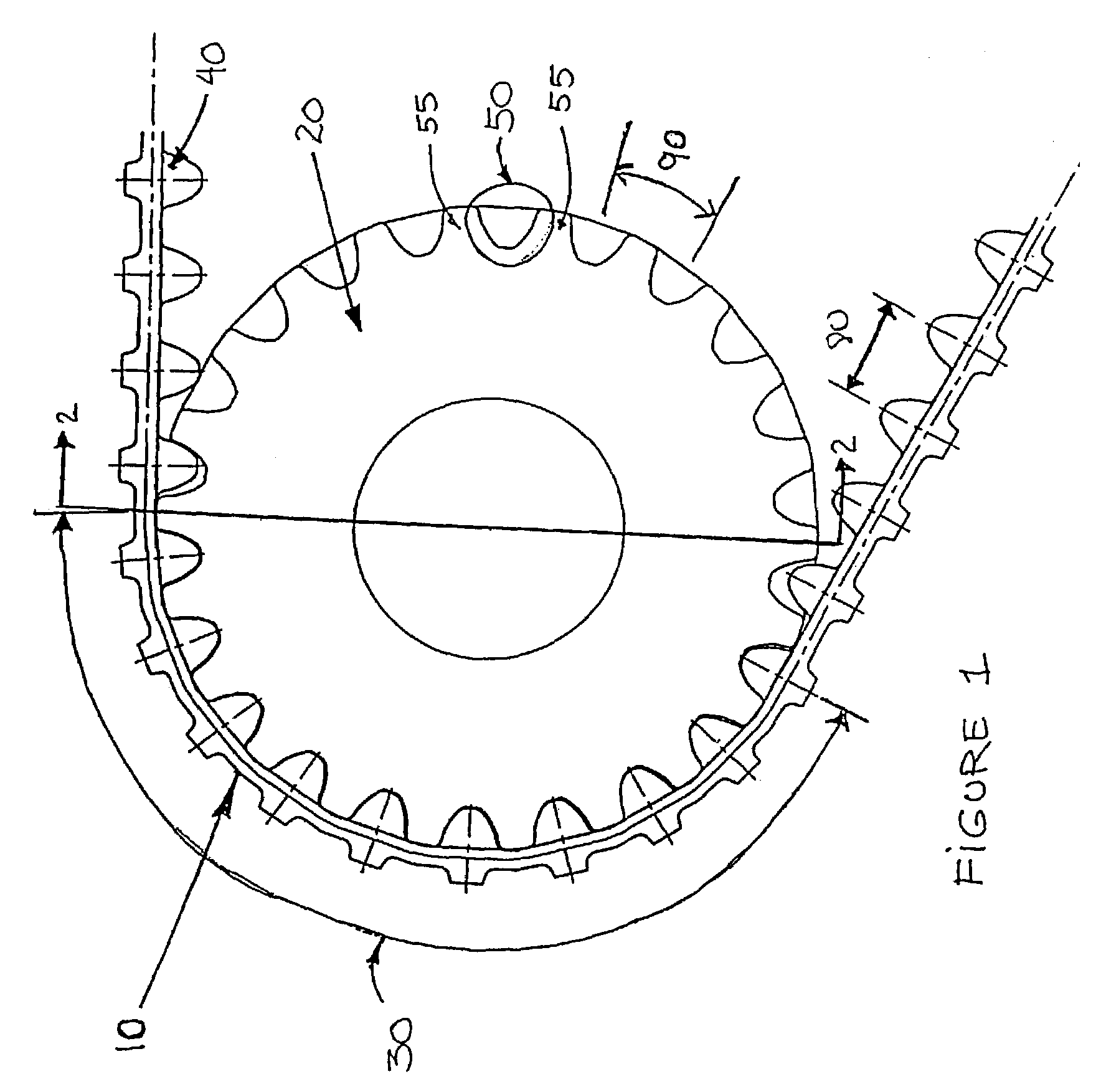
[0024]FIG. 1 shows a typical reinforced elastomeric traction band 10 made from UHMW-PE (or polymeric material of low friction coefficient and abrasion resistant) and mounted around a sprocket 20 on a vehicle. The traction band 10 under tension is in contact with the sprocket 20 along an arc or angular meshing range 30, which generally spans from 30 to 180 degrees, and linearly extends before and after the arc 30. As seen in FIG. 1, the sprocket 20 is a wheel with a succession of teeth 55 and cavities 50. It is rigidly coupled to a transmission shaft, principally to transmit power from the engine (not shown) to the traction band 10, which explains the importance of a firm cohesion or meshing between the traction lugs 40 of the traction band 10 and the corresponding cavities 50 of the sprocket 20. In this example, there are twenty-two cavities 50, and ten of them are meshed with their corresponding traction lugs 40 at any given time. Theoretically, only one meshed traction lug 40 can ...


PUM


Abstract

This invention refers to the traction lugs of reinforced elastomeric endless traction bands, and more particularly to those which are used on heavy vehicles like defense vehicles or for skid steer vehicles. More specifically, the invention relates to traction lugs which are angled with respect to the transversal axis of the traction band and preferably disposed in chevrons, which optimize the band's traction while reducing the occurrences of teeth skipping and the level of vibrations and noise induced by the interaction of the traction band with the sprocket.

Description

FIELD OF INVENTION[0001]This invention refers to the drive lugs of reinforced elastomeric endless traction bands, and more particularly to those which are used on heavy vehicles like defense vehicles. More specifically, the invention relates to traction lugs which are angled with respect to the transversal axis of the traction band.BACKGROUND OF THE INVENTION[0002]Heavy tracked vehicles and skid steer vehicles benefit from numerous advantages coming from the use of bands when traction is needed, when compared to the sole use of wheels. One of the most important advantages is the provision of a better traction on all types of soil: rocky, uneven, muddy or covered with snow, etc. When traction is ensured via the use of a band, a sprocket usually transmits mechanical power from the engine to the traction band, which in turns transmits this power to the ground to provide movement to the vehicle. Therefore, the traction band's efficiency greatly relies on the interaction between the spro...

Claims


Application Information

Patent Timeline
Patent Type & Authority Patents(United States)
IPC IPC(8): B62D55/205B62D55/24
CPCB62D55/244
Inventor DELAND, ANDREDELISLE, MARC
Owner SOUCY INT
Why Eureka
Try Eureka