Aeration apparatus and method

a technology of aeration apparatus and impeller, which is applied in the direction of machines/engines, liquid fuel engines, transportation and packaging, etc., can solve the problems of very inefficient processes in both time consumption and energy consumption, and achieve the effects of improving the aeration efficiency of the impeller, and high aeration efficiency

Active Publication Date: 2006-10-03
SPX FLOW INC
View PDF22 Cites 34 Cited by
  • Summary
  • Abstract
  • Description
  • Claims
  • Application Information

AI Technical Summary

Benefits of technology

[0006]The present invention relates to impellers which are especially adapted for use in surface aeration of liquids in a tank when disposed on the surface of the liquid in the tank. More particularly, the present invention relates to an improved surface aeration impeller which has hydraulic performance which lends itself to high efficiency of aeration in terms of the mass of oxygen transferred to the liquid per applied energy per unit time. It has been discovered in accordance with the present invention that the aeration efficiency of an impeller can be improved by modifying the spray pattern of the impeller employed in the aeration process, by curving the top portions of the blades that make up the impeller. It also has been discovered that by providing an opening or slot on the impeller blades through which a portion of liquid may pass, aeration efficiency of the impeller can be improved.

Problems solved by technology

A disadvantage of the above described aeration process is that it is very inefficient.
This time period combined with the fact that these waste treatment processes are oftentimes carried out continuously year round, provide a process that is very inefficient in terms of both time consumption and energy consumption.

Method used


Image

  • Aeration apparatus and method
  • Aeration apparatus and method
  • Aeration apparatus and method

Examples


Embodiment Construction

[0031]The present invention provides an apparatus and method for mass transfer of gas and / or air into a liquid and / or liquid suspension. The present invention is preferably used in conjunction with waste treatment processes and / or fermentation processes that are commonly carried out in a mixing vessel. In such an arrangement, the mass transfer process is utilized to contact gas and / or oxygen containing gas to a liquid in a mixing vessel or aeration basin. It should be understood, however, that the present invention is not limited in its application to waste treatment, but, for example, can be used with other processes requiring liquid aeration or gas transfer.

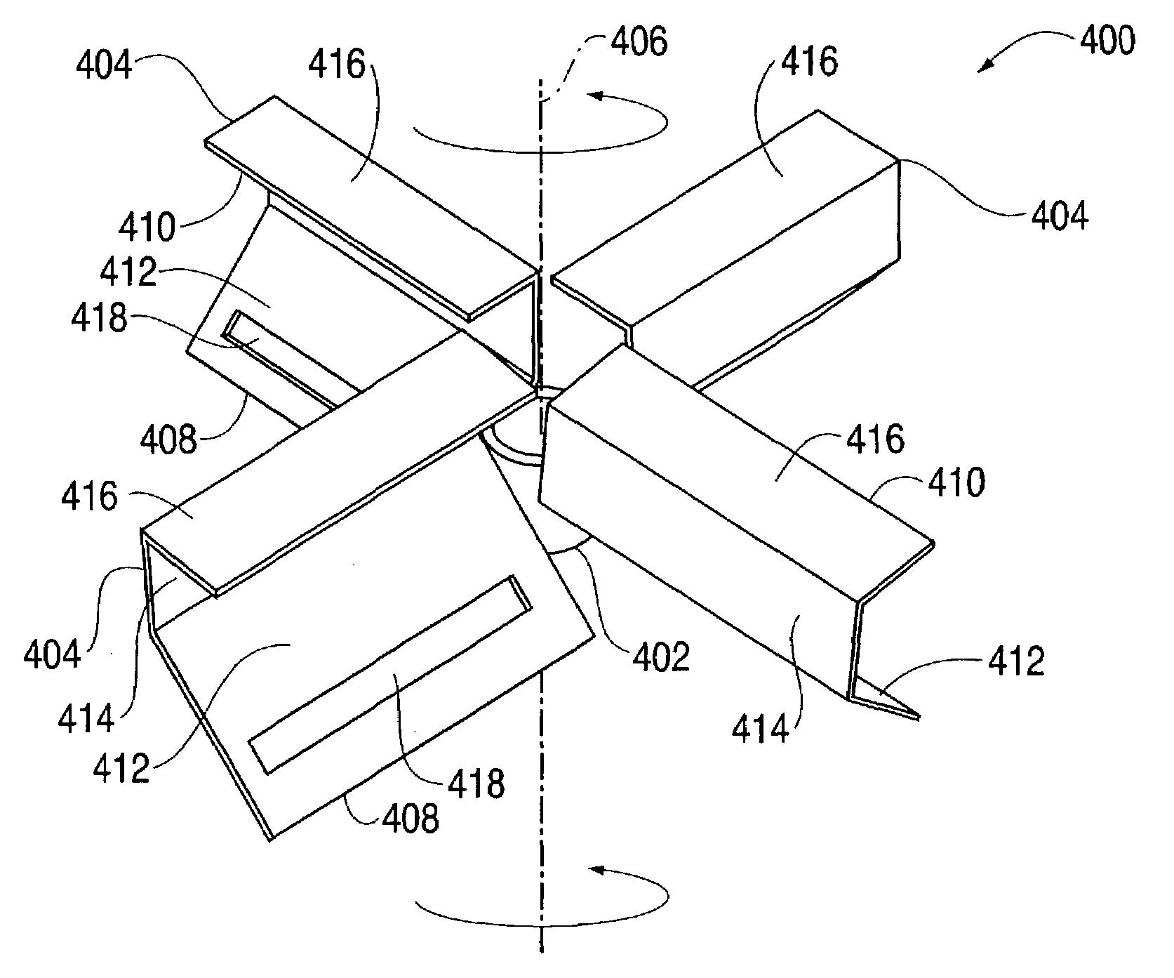
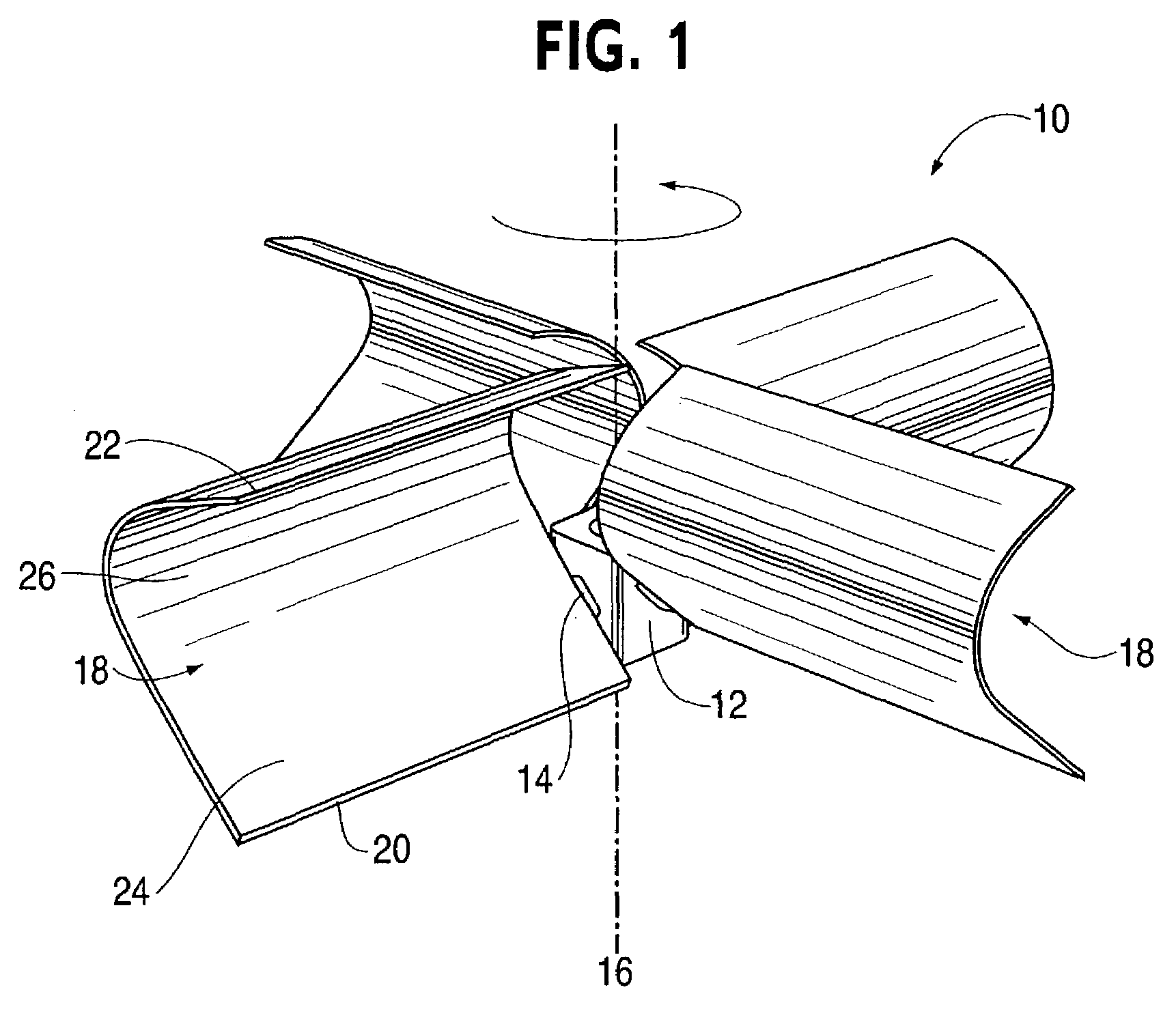
[0032]Referring now to the figures, wherein like reference numerals indicate like elements, FIG. 1 shows a perspective view of a surface aeration impeller 10 in accordance with an embodiment of the present invention. The surface aeration impeller 10 includes a hub 12 that rotates preferably with a shaft (not pictured) of a mixe...


PUM

PropertyMeasurementUnit
angleaaaaaaaaaa
angleaaaaaaaaaa
angleaaaaaaaaaa

Abstract

The present invention provides an improved aeration impeller for use in a mixing assembly having an axis of rotation. The aeration impeller includes a hub and a first and second blades that are connected to the hub. Each blade has a first portion positioned at an angle to the axis of rotation and a second portion positioned at an angle to the first portion. The first portion of each blade has an opening that at least partially extends the width of the first portion.

Description

FIELD OF THE INVENTION[0001]The present invention relates to an improved aeration apparatus and method. More particularly, the present invention relates to an apparatus and method that relates to impellers. The invention is useful, for example, for use in wastewater treatment plants for introducing oxygen into wastewater where the oxygen is used by biological elements that digest the waste. The invention is also useful in various other processes where the transfer of gas and / or oxygen is required.BACKGROUND OF THE INVENTION[0002]In mass transfer processes such as waste treatment and bio-reactions, it is common to carry out these processes in an aeration vessel in which gas, such as oxygen and / or air, is introduced into a biodegradable liquid for treatment. These aforementioned processes are oftentimes utilized by municipalities and industry to treat waste water wherein the object of the process is to introduce air to the liquid and then the micro-organisms in the liquid proceed to u...

Claims


Application Information

Patent Timeline
Patent Type & Authority Patents(United States)
IPC IPC(8): B01F7/16B01F3/04B01F7/00B01F15/00
CPCB01F3/0478B01F7/00275B01F2215/0422B01F23/234211B01F27/1123
Inventor WEETMAN, RONALD J.
Owner SPX FLOW INC
Why Eureka
Try Eureka