Transceiver module

a transceiver module and module technology, applied in the direction of optical elements, coupling device connections, instruments, etc., can solve the problems of increasing installation cost and/or repair time, preventing the operator from removing the transceiver module, and inconvenient removal of the transceiver modul

Active Publication Date: 2006-10-03
LUMENTUM OPERATIONS LLC
View PDF22 Cites 49 Cited by
  • Summary
  • Abstract
  • Description
  • Claims
  • Application Information

AI Technical Summary

Benefits of technology

[0010]Another object of the present invention is to provide an easily operable release mechanism at minimal cost.
[0013]Yet a further object of the present invention is to provide a release and removal mechanism that can be easily assembled.
[0014]Yet a further object of the present invention is to provide a release and removal mechanism for a transceiver module that does not increase the overall height and width of the transceiver module.
[0015]Yet a further object of the present invention is to provide a delatch mechanism that is easy to manufacture.
[0016]Yet a further object of the present invention is to provide a delatch mechanism that is relatively robust in construction.

Problems solved by technology

The requirement of a tool for removing the transceiver module is not only inconvenient, but also prevents an operator from removing a transceiver module if he or she does not have a tool at the appropriate time.
The requirement of a tool results in increased installation cost and / or repair time.
However, the mechanism described in this patent employs a delatch mechanism that is relatively difficult to manufacture and is relatively fragile in construction.

Method used


Image

  • Transceiver module
  • Transceiver module
  • Transceiver module

Examples


Embodiment Construction

[0067]It is advantageous to define several terms before describing the invention. It should be appreciated that the following definitions are used throughout this application.

DEFINITIONS

[0068]Where the definition of terms departs from the commonly used meaning of the term, applicant intends to utilize the definitions provided below, unless specifically indicated.

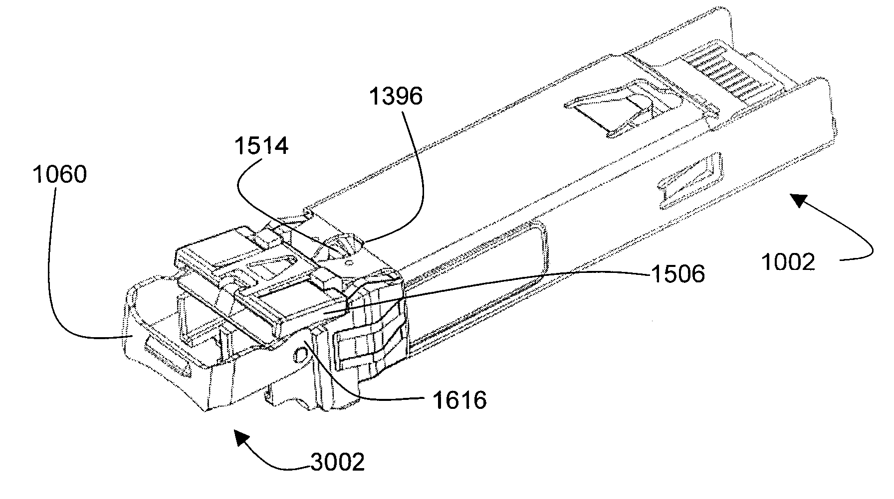
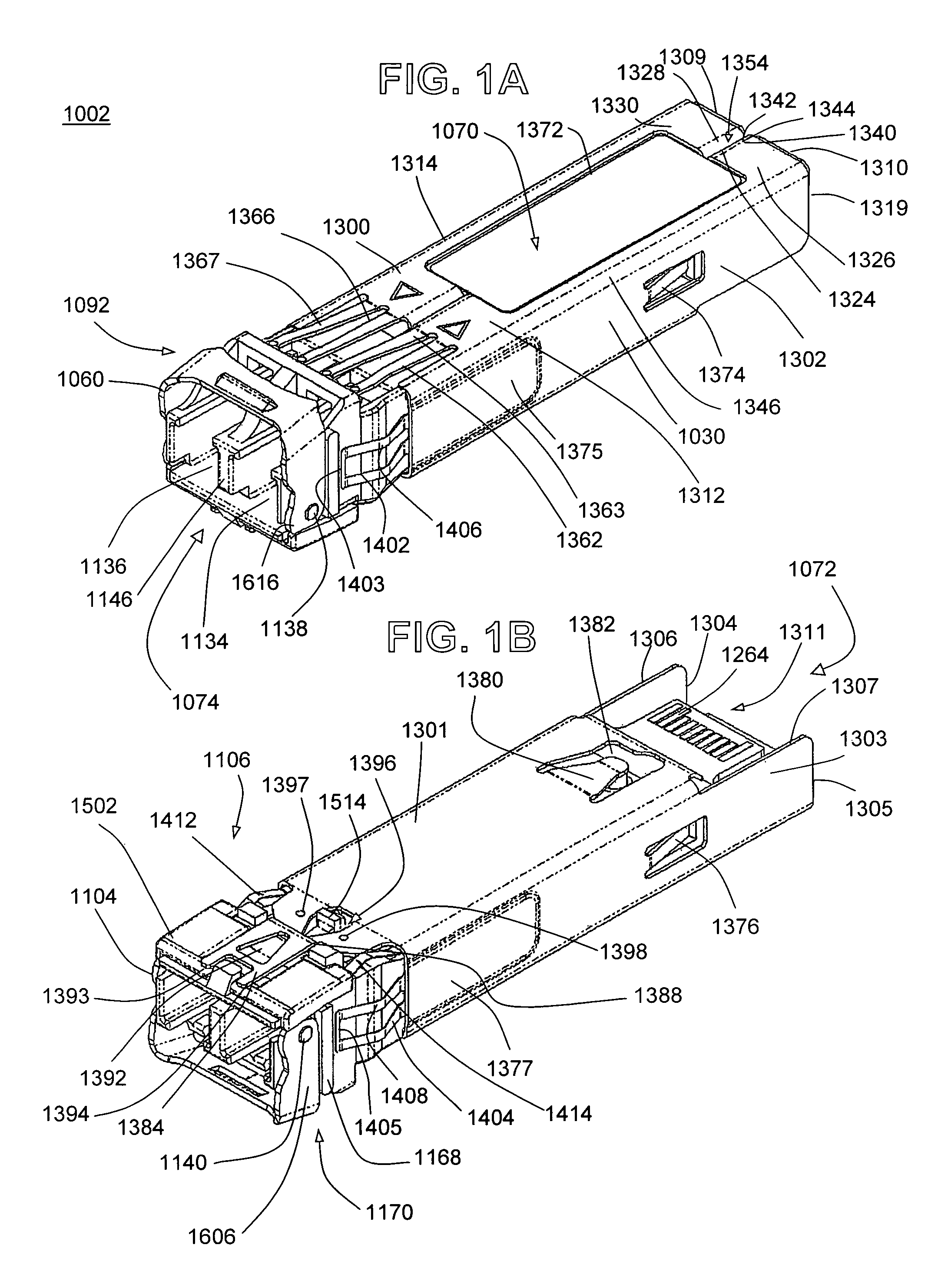
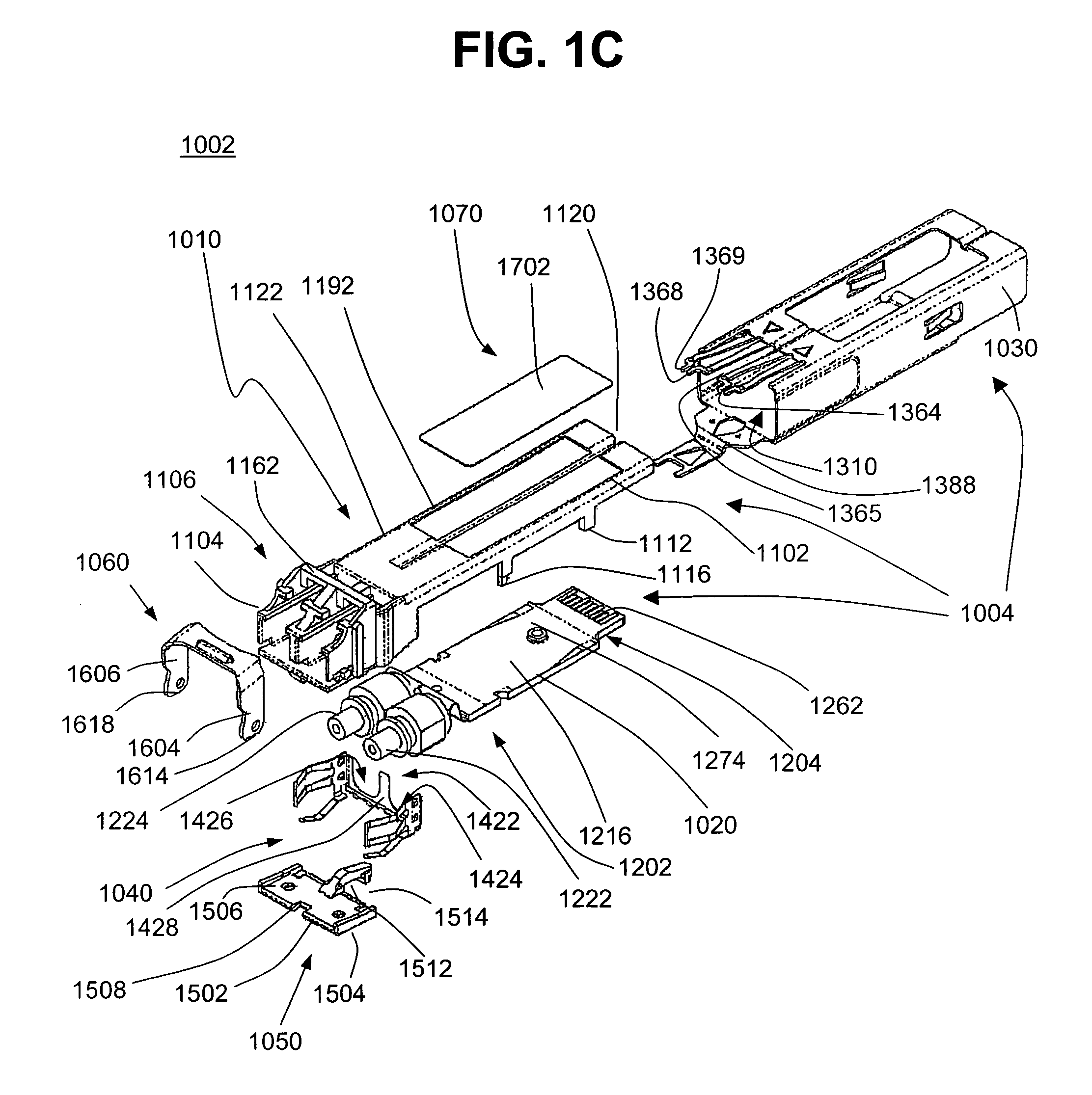
[0069]For the purposes of the present invention, the term “transceiver” refers to an electrical or optical transmitter, an electrical or optical receiver, or an electrical or optical transceiver. Unless otherwise specified, a “transceiver” refers to an optical transceiver comprising two ports, one port comprising a transmit port and one port comprising a receive port.

[0070]For the purposes of the present invention, the term “proximal” refers to the end of a transceiver housing or transceiver cage in which an optical receptacle is mounted.

[0071]For the purposes of the present invention, the term “distal” refers to the end of ...


PUM


Abstract

The present invention provides transceiver modules in which a transceiver may be ejected from a cage into which the transceiver is inserted by pivoting a handle mounted on the transceiver.

Description

BACKGROUND OF THE INVENTION[0001]1. Field of the Invention[0002]The present invention relates to transceiver modules for use with transceiver cages.[0003]2. Description of the Prior Art[0004]Optoelectronic transceivers are utilized to interconnect circuit cards of communication links and other electronic modules or assemblies. Various international and industry standards define the type of connectors used to interface computers to external communication devices such as modems, network interfaces, and other transceivers. A well-known type of transceiver module developed by an industry consortium and known as a Gigabit Interface Converter (GBIC) provides an interface between a computer and an Ethernet, Fiber Channel, or other data communication environment. U.S. patents identified under issued U.S. Pat. Nos. 5,879,173, 5,864,468, 5,734,558, 5,717,533, and U.S. Pat. No. Re 36,820, originally assigned to Methode Electronics, Inc, and now assigned to Stratos Lightwave, both in Chicago, I...

Claims


Application Information

Patent Timeline
Patent Type & Authority Patents(United States)
IPC IPC(8): G02B6/36G02B6/40
CPCG02B6/4246H01R13/6275G02B6/3893G02B6/3897H01R13/6335G02B6/4284
Inventor KAYNER, ANDREWMOORE, ANDREWTOWER, SUSANRENOUX, GERALDYUNKER, BRYAN
Owner LUMENTUM OPERATIONS LLC
Why Eureka
Try Eureka