
Measurement to determine plasma leakage

a plasma leakage and measurement technology, applied in the direction of individual semiconductor device testing, semiconductor/solid-state device testing/measurement, instruments, etc., can solve the problem of onset of plasma leakage at a specific power level

Inactive Publication Date: 2006-10-03
IBM CORP
View PDF22 Cites 5 Cited by
  • Summary
  • Abstract
  • Description
  • Claims
  • Application Information

AI Technical Summary

Benefits of technology

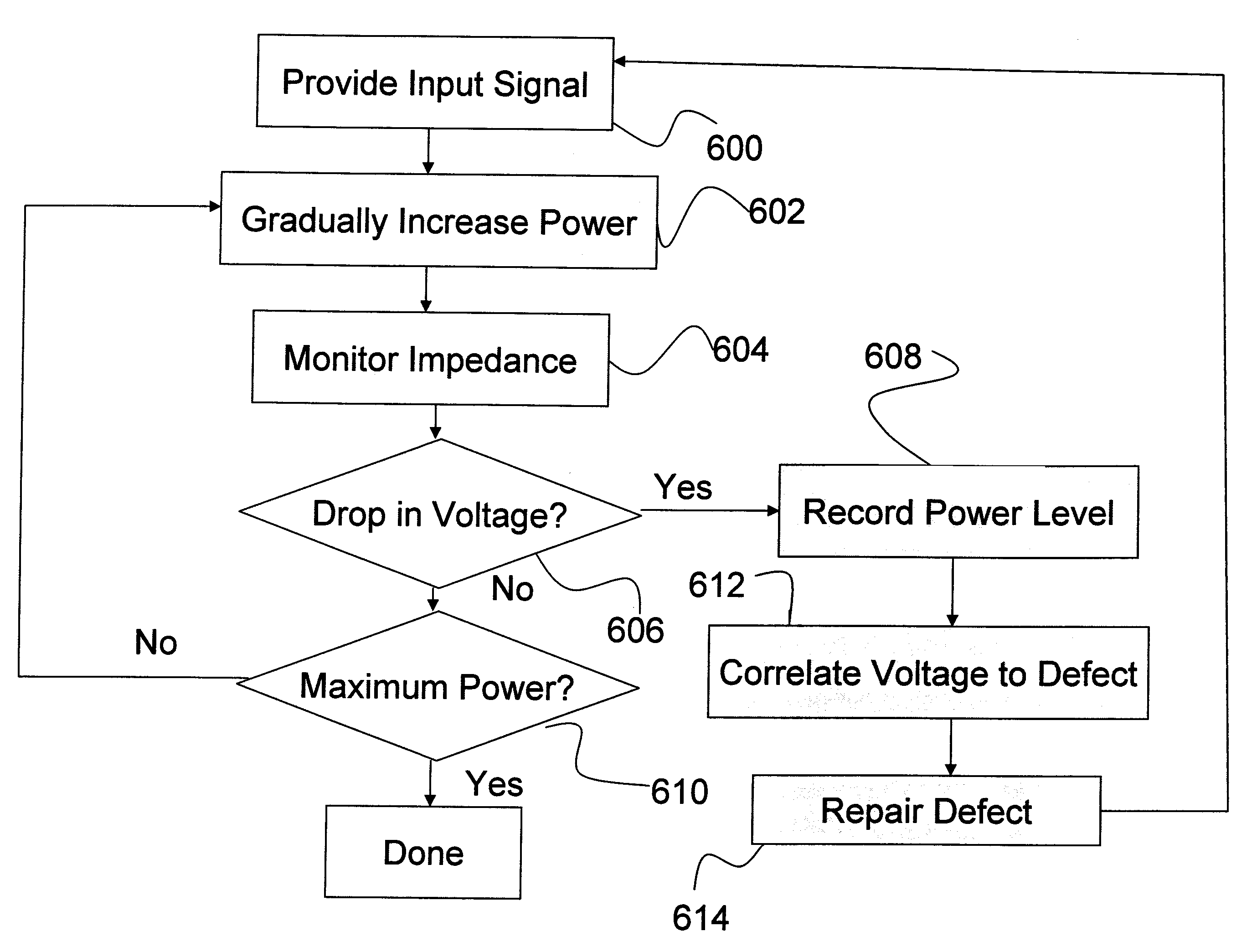
The present invention provides a method and system for detecting abnormal plasma discharge in a chamber, particularly plasma leakage in a reactive ion etching chamber. The system uses electrical contacts connected to the chamber and a variable power controller to gradually increase the power of the input signal. An impedance monitor monitors the impedance of the chamber to determine the voltage of the chamber and an abrupt drop in peak-to-peak voltage indicates plasma leakage. The invention also records the power level at which plasma leakage occurs and correlates it with specific types of chamber defects. This allows for quicker diagnosis of defects and periodic testing of the chamber.

Problems solved by technology

In other words, some defects will consistently cause the onset of plasma leakage to occur at a specific power level.

Method used


Image

  • Measurement to determine plasma leakage
  • Measurement to determine plasma leakage
  • Measurement to determine plasma leakage

Examples


Embodiment Construction

[0017]The present invention and the various features and advantageous details thereof are explained more fully with reference to the nonlimiting embodiments that are illustrated in the accompanying drawings and detailed in the following description. It should be noted that the features illustrated in the drawings are not necessarily drawn to scale. Descriptions of well-known components and processing techniques are omitted so as to not unnecessarily obscure the present invention. The examples used herein are intended merely to facilitate an understanding of ways in which the invention may be practiced and to further enable those of skill in the art to practice the invention. Accordingly, the examples should not be construed as limiting the scope of the invention.

[0018]As mentioned above, when plasma leakage occurs in an etching chamber, this results in power loss in the primary plasma location within the chamber, which degrades the etching process. The present inventors have develop...


PUM

PropertyMeasurementUnit
monitoring impedanceaaaaaaaaaa
impedanceaaaaaaaaaa
radio frequencyaaaaaaaaaa

Abstract

Disclosed is a method and system for detecting abnormal plasma discharge that is useful in, for example, detecting plasma leakage in a reactive ion etching (RIE) chamber. The system includes electrical contacts connected to the chamber that provide an input signal to the chamber. This input signal can be generated by a radio frequency (RF) generator that is connected to the electrical contacts. A variable power controller connected to the RF generator gradually increases (ramps) the power of the input signal being supplied to the chamber.

Description

BACKGROUND OF INVENTION[0001]1. Field of the Invention[0002]The present invention relates to a method and system for detecting abnormal plasma discharge that is useful in, for example, detecting plasma leakage in a reactive ion etching (RIE) chamber.[0003]2. Description of the Related Art[0004]When performing processing in a chamber, such as reactive ion etching (RIE) within a plasma chamber, various problems can occur that affect the quality of the processing performed in the chamber. One problem that can occur is plasma leakage. More specifically, plasma leakage occurs when secondary plasma is formed in locations of the reactor other than the desired region. The source of the plasma leakage can be attributed to a variety of factors, some of which are difficult to monitor (e.g., baffle reworking, bad electrical contact of various parts, worn quartz rings, etc.). This plasma leakage degrades performance and sometimes results in failures because of problems such as vertical leakage a...

Claims


Application Information

Patent Timeline
Patent Type & Authority Patents(United States)
IPC IPC(8): G01L21/30G01M3/40G01R31/00H01J37/32
CPCG01M3/40H01J37/32174H01J37/32935H01J2237/0206
Inventor CALDERONI, ROBERT A.CLINE, JUNEDUTRA, KELLIE L.MEUNIER, RONALD G.WALKO, JOSEPH P.WONG, JUSTIN WAI-CHOW
Owner IBM CORP
Learn More