Mounting structure, electro-optical device, and electronic apparatus
a technology of electrooptical devices and mounting structures, applied in the direction of optics, circuit bendability/strength, instruments, etc., can solve the problems of easy breakage of wiring lines on flexible substrates, and difficult to prevent the breakage of flexible substrates at fragile boundary. achieve the effect of reliably preventing the breakag
- Summary
- Abstract
- Description
- Claims
- Application Information
AI Technical Summary
Benefits of technology
Problems solved by technology
Method used
Image
Examples
first embodiment
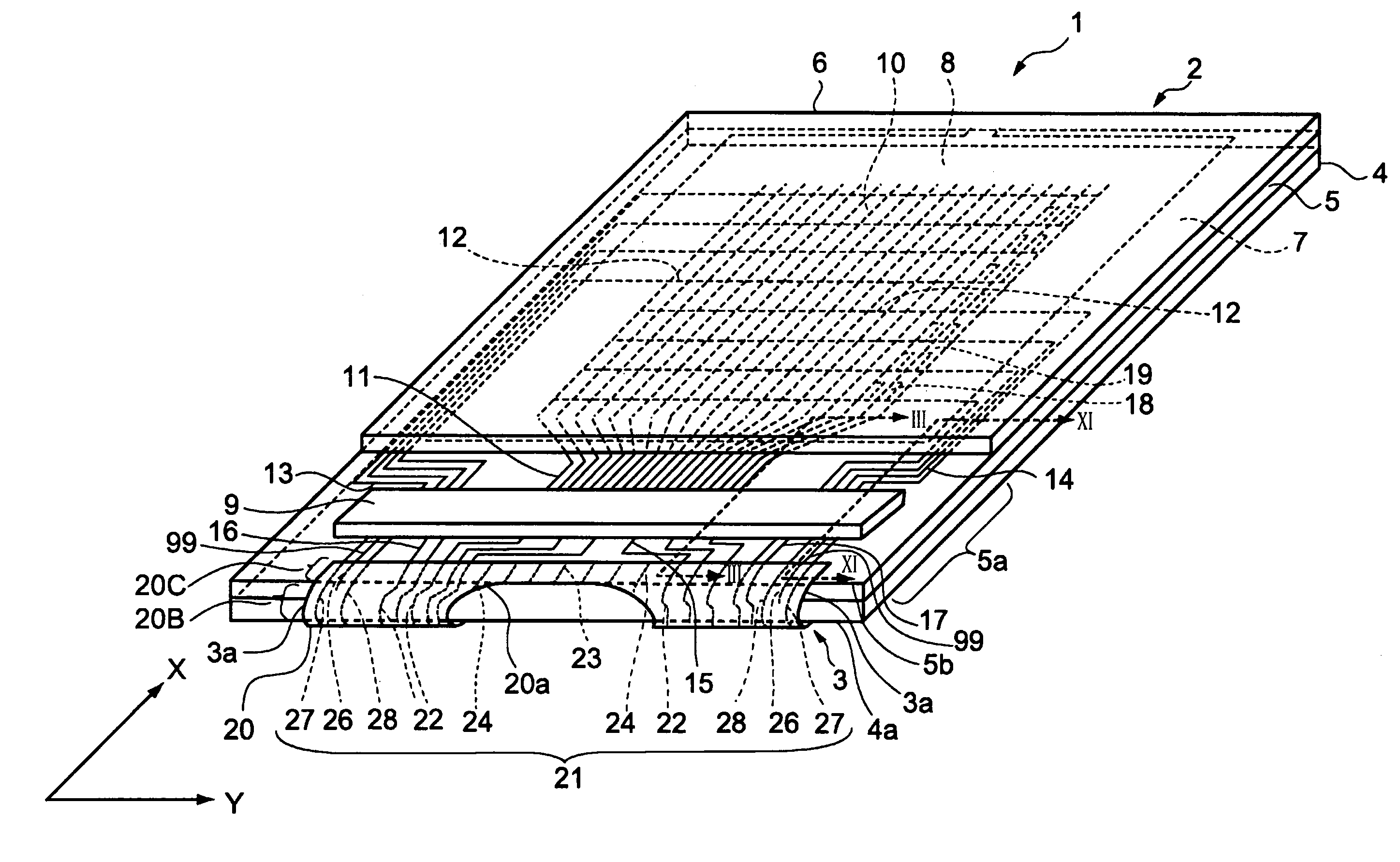
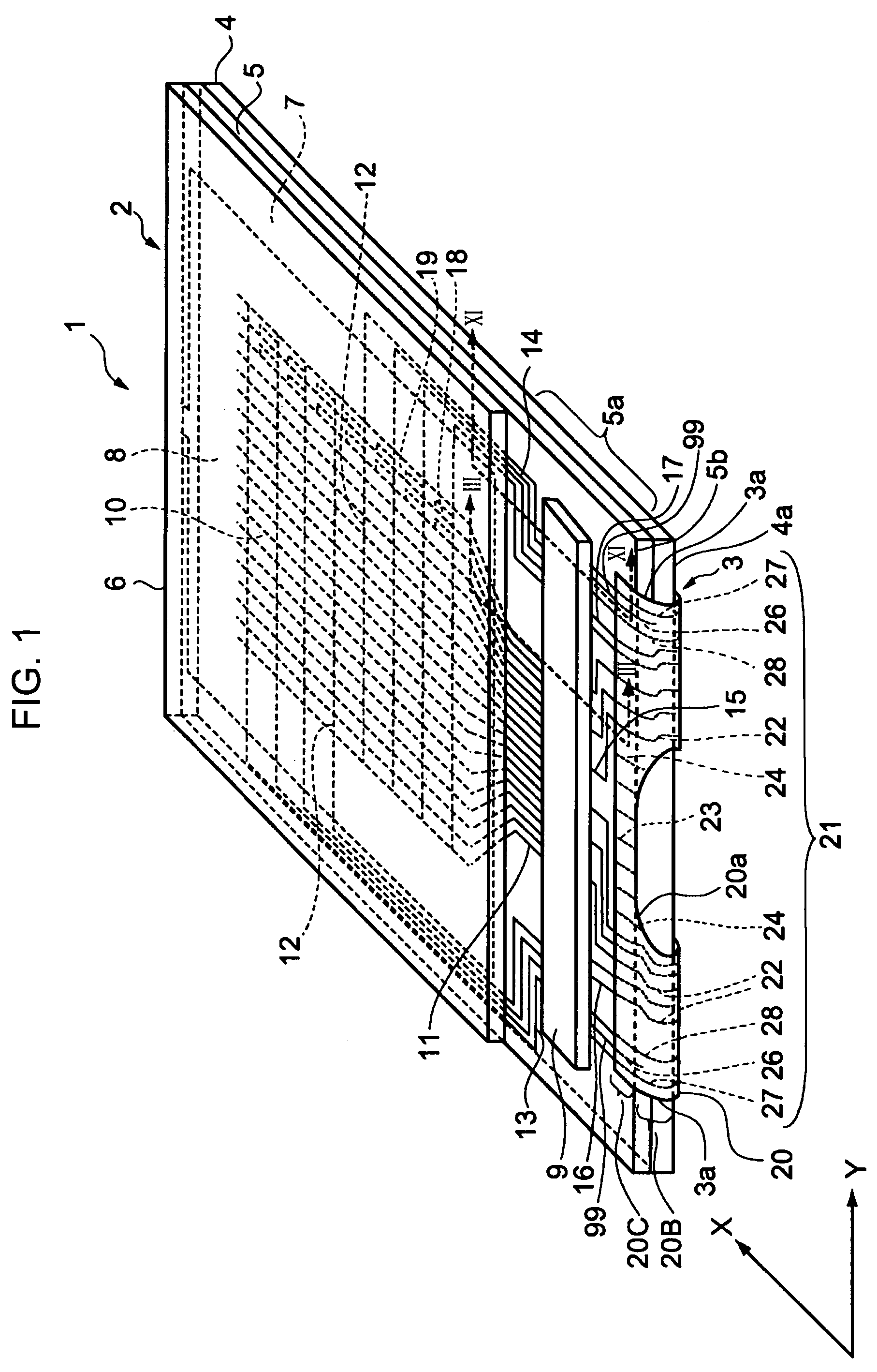
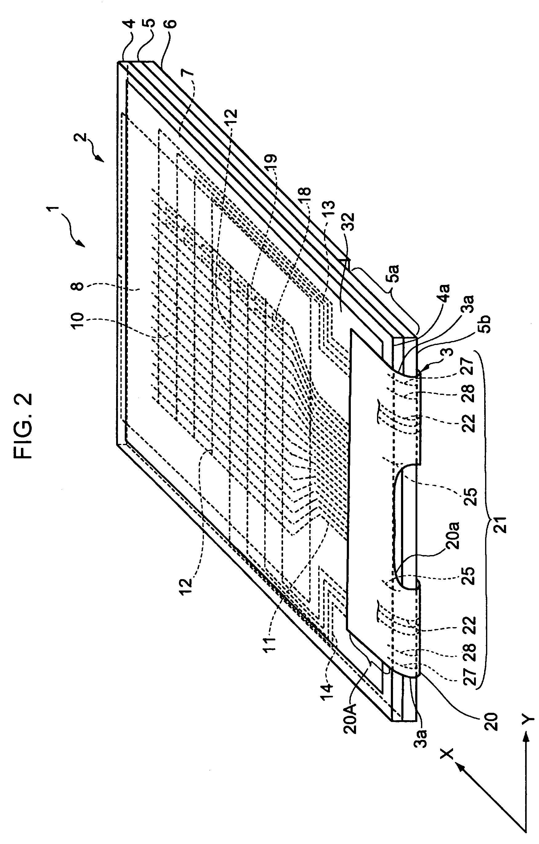
[0046]FIG. 1 is a schematic perspective view illustrating a liquid crystal display device of the first embodiment according to the invention. FIG. 2 is a schematic perspective view illustrating the liquid crystal display device, seen from the bottom surface. FIG. 3 is a cross-sectional view illustrating the liquid crystal display device shown in FIG. 1 taken along the line III—III.
[0047]The liquid crystal display device 1 of the present embodiment is provided with a liquid crystal panel 2, a circuit board 3 serving as a second substrate connected to the liquid crystal panel 2, and a frame 4 serving as a frame body which supports the liquid crystal panel 2. Moreover, other mechanisms to be described below, if necessary, are attached to the liquid crystal display device 1.
[0048]The liquid crystal panel 2 is provided with a rectangular substrate 5 serving as a first substrate, a substrate 6 provided to face the substrate 5, a sealing material 7 provided between the substrates 5 and 6, ...
second embodiment
[0090]Next, a liquid crystal display device of the second embodiment according to the invention will be described. Moreover, in embodiments and modifications following the present embodiment, the same numerals are attached to the same constituent members as those of the above-described embodiment, and the descriptions thereof will be omitted. Different portions will be focused to be described.
[0091]FIG. 5 is a schematic perspective view illustrating the liquid crystal display device of the second embodiment according to the invention, and FIG. 6 is a schematic plan view illustrating a FPC substrate which is used in a liquid crystal panel shown in FIG. 5.
[0092]In the liquid crystal display device 40 of the present embodiment, a circuit board 41 having a different shape from the circuit board 3 is used instead of the circuit board 3, as shown in FIG. 5.
[0093]The circuit board 41 includes a FPC substrate 42 and a wiring group 43 provided on the FPC substrate 42.
[0094]As shown in FIG. 6...
third embodiment
[0100]Next, a liquid crystal device of the third embodiment according to the invention will be described.
[0101]FIG. 7 is a schematic plan view illustrating a circuit board which is used in the liquid crystal display device of the present embodiment.
[0102]The liquid crystal display device of the present embodiment is an example in which a circuit board 50 is used instead of the circuit board 3. On the circuit board 50, dummy wiring lines are provided to have different widths in the direction crossing the extending direction thereof.
[0103]The circuit board 50 includes a FPC substrate 51 composed of a mounting portion 51A, a bending portion 51B, and an end portion 51C, similar to the above-described embodiment. Further, the circuit board 50 includes dummy wiring lines 52, 53, 54, 55, and 56 which have different widths from the above-described wiring lines in the Y direction crossing the extending direction.
[0104]The dummy wiring line 52, which is provided in an island shape (plate tabl...
PUM
 Abstract
Description
Claims
Application Information
 - R&D
- Intellectual Property
- Life Sciences
- Materials
- Tech Scout
- Unparalleled Data Quality
- Higher Quality Content
- 60% Fewer Hallucinations
Browse by: Latest US Patents, China's latest patents, Technical Efficacy Thesaurus, Application Domain, Technology Topic, Popular Technical Reports.
© 2025 PatSnap. All rights reserved.Legal|Privacy policy|Modern Slavery Act Transparency Statement|Sitemap|About US| Contact US: help@patsnap.com


