
Apparatus and method for accurately tuning the speed of an integrated circuit

a technology of integrated circuits and speed tuning, applied in the direction of pulse characteristics measurement, pulse automatic control, instruments, etc., can solve problems such as slack in the monitored path, and achieve the effect of accurate tuning the speed of an integrated circui

Active Publication Date: 2006-10-03
IBM CORP
View PDF5 Cites 23 Cited by
  • Summary
  • Abstract
  • Description
  • Claims
  • Application Information

AI Technical Summary

Benefits of technology

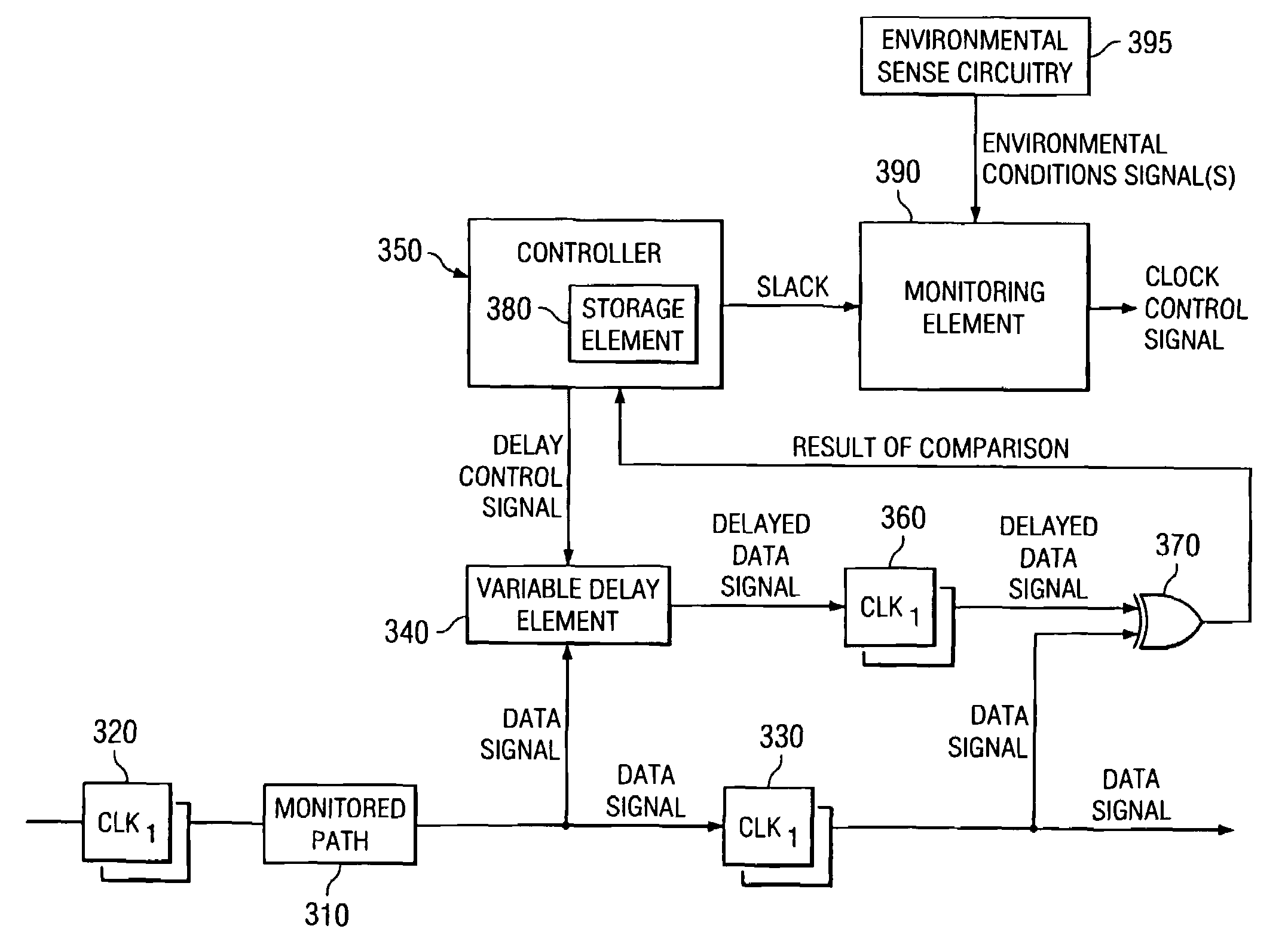
The present invention provides a mechanism for accurately tuning the speed of an integrated circuit using a built-in sense circuit and controller. The sense circuit adds a variable delay element to a path in the integrated circuit before a first capture latch. The delayed data signal is provided to a second capture latch, which compares it with the output of the first capture latch using an exclusive OR gate. The output of the exclusive OR gate is provided to the controller for informing it of the results of the comparison. The invention can be used to determine the amount of slack in the monitored path, which indicates the amount of delay before the path becomes non-functional. The invention can also be used in combination with other sensing elements to address reliability or safety concerns.

Problems solved by technology

The delay setting just prior to this miscompare represents the slack in the monitored path.

Method used


Image

  • Apparatus and method for accurately tuning the speed of an integrated circuit
  • Apparatus and method for accurately tuning the speed of an integrated circuit
  • Apparatus and method for accurately tuning the speed of an integrated circuit

Examples


Embodiment Construction

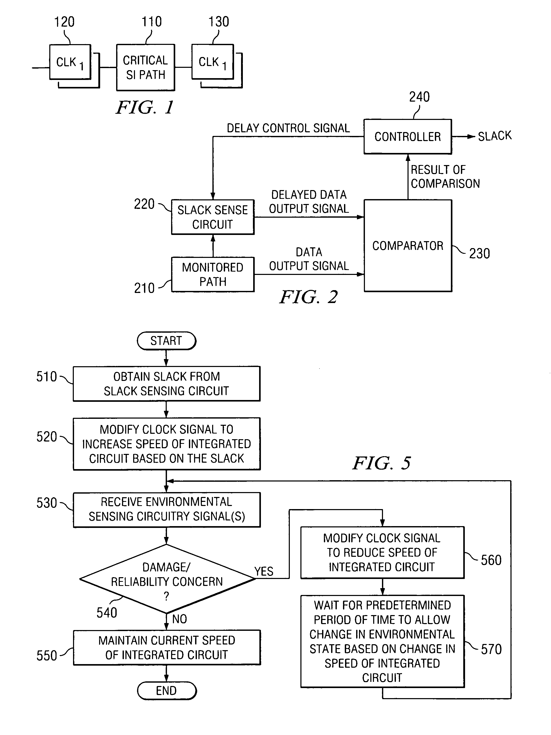
[0023]FIG. 1 is an exemplary diagram illustrating a timing flow of critical path of an integrated circuit or computer chip. For purposes of this description, the terms “integrated circuit” and “chip” are used interchangeably. Under worse case conditions (e.g., slow process, high temperature, low power supply), the critical path limits the speed of the integrated circuit or computer chip. In a conventional design the integrated circuit would be sorted into “speed buckets” based on a manufacturing test, such as an AC BIST. Faster chips are sold at a premium relative to slower chips. Typically, the upper speed is fixed and guaranteed over a specified temperature and supply voltage range.

[0024]If a customer operates the chip, or the system in which the chip is implemented, at below the maximum allowed temperature and / or above the minimum allowed power supply, there would be a significant amount of timing margin, i.e. the difference between the identified speed of the chip and the maximu...


PUM


Abstract

An apparatus and method for accurately tuning the speed of an integrated circuit, i.e. a computer chip, using a built-in sense circuit and controller are provided. The sense circuit is provided in association with a monitored path. The sense circuit includes a variable delay element coupled to a controller. A data signal from the monitored path is provided to the sense circuit which adds an amount of delay as determined by the controller to the data signal. The delayed data signal and the original data signal are compared to determine if their values match. If they match, then the amount of delay added by the variable delay element is increased. If they do not match, then a previous amount of delay, prior to the mismatch, is output as the slack of the monitored path. The slack may then be used to tune the speed of the integrated circuit.

Description

BACKGROUND OF THE INVENTION[0001]1. Technical Field[0002]The present invention is generally directed to an improved mechanism for sensing a maximum speed of a path in an integrated circuit and controlling operation of the integrated circuit timing based on the sensed maximum speed. More specifically, the present invention is directed to an apparatus and method for accurately tuning the speed of a computer chip using a built-in sense circuit and controller.[0003]2. Description of Related Art[0004]When integrated circuits, or chips, are manufactured, due to inaccuracies in the manufacturing methodology the integrated circuits need to be tested to determine their actual operational characteristics. Typically, these chips are sorted at the device level to segregate them into performance ranges, e.g., slow, medium and fast with respect to their expected operational speed.[0005]The testing of these chips is typically performed with regard to the critical path or paths of the chip. That is...

Claims


Application Information

Patent Timeline
Patent Type & Authority Patents(United States)
IPC IPC(8): H03L7/06
CPCG01R31/31725
Inventor FERRAIOLO, FRANK DAVIDFIELDS, JR., JAMES STEPHENJAMES, NORMAN KARLMCCREDIE, BRADLEY DAVID
Owner IBM CORP
Learn More