Hydrophone mandrel for precise placement of gratings

a technology of mandrels and hydrophones, which is applied in the direction of instruments, optical elements, force measurement by measuring optical property variation, etc., can solve the problems of excessive shift in the center frequency of the bragg wavelength, no longer highly reflective bragg gratings at the correct wavelength, and the bragg gratings themselves should be protected. to achieve the effect of accurate positioning

Inactive Publication Date: 2006-10-03
WEATHERFORD TECH HLDG LLC
View PDF12 Cites 15 Cited by
  • Summary
  • Abstract
  • Description
  • Claims
  • Application Information

AI Technical Summary

Benefits of technology

[0009]One embodiment that is in accord with the principles of the present invention is a mandrel that reduces the difficulty of wrapping an optical waveguide Bragg grating interferometer such that the Bragg gratings are accurately positioned. Such a mandrel has at least two outer diameters.
[0010]Another embodiment that is in accord with the principles of the present invention is a bored mandrel that reduces the difficulty of wrapping an optical waveguide Bragg grating interferometer on the mandrel such that the Bragg gratings are accurately positioned within bores. Such a mandrel has at least two outer diameters and a bore for receiving a section of an optical waveguide that includes a Bragg grating.
[0011]Another embodiment of the present invention is an interferometric hydrophone having Bragg gratings that are physically protected in a bore or bores of a mandrel having at least two outer diameters. The mandrel enables controlled routing of the optical waveguide to prevent excessive optical loss while protecting the Bragg gratings from physical damages due to shock and vibration.

Problems solved by technology

One issue with mandrel-based optical waveguide, Bragg grating acoustic sensors is that the Bragg gratings themselves should be protected.
Strain on the Bragg gratings can cause an excessive shift in the center frequency of the Bragg wavelength such that the Bragg gratings are no longer highly reflective at the correct wavelength.
However, manufacturing tolerances may lead to significant variations in length between the gratings.
Thus, it is difficult to tightly wrap an optical waveguide around a cylindrical mandrel while positioning the Bragg gratings inside the mandrel (which may require a precision of + / −0.040 inch to do).

Method used


Image

  • Hydrophone mandrel for precise placement of gratings
  • Hydrophone mandrel for precise placement of gratings
  • Hydrophone mandrel for precise placement of gratings

Examples


Embodiment Construction

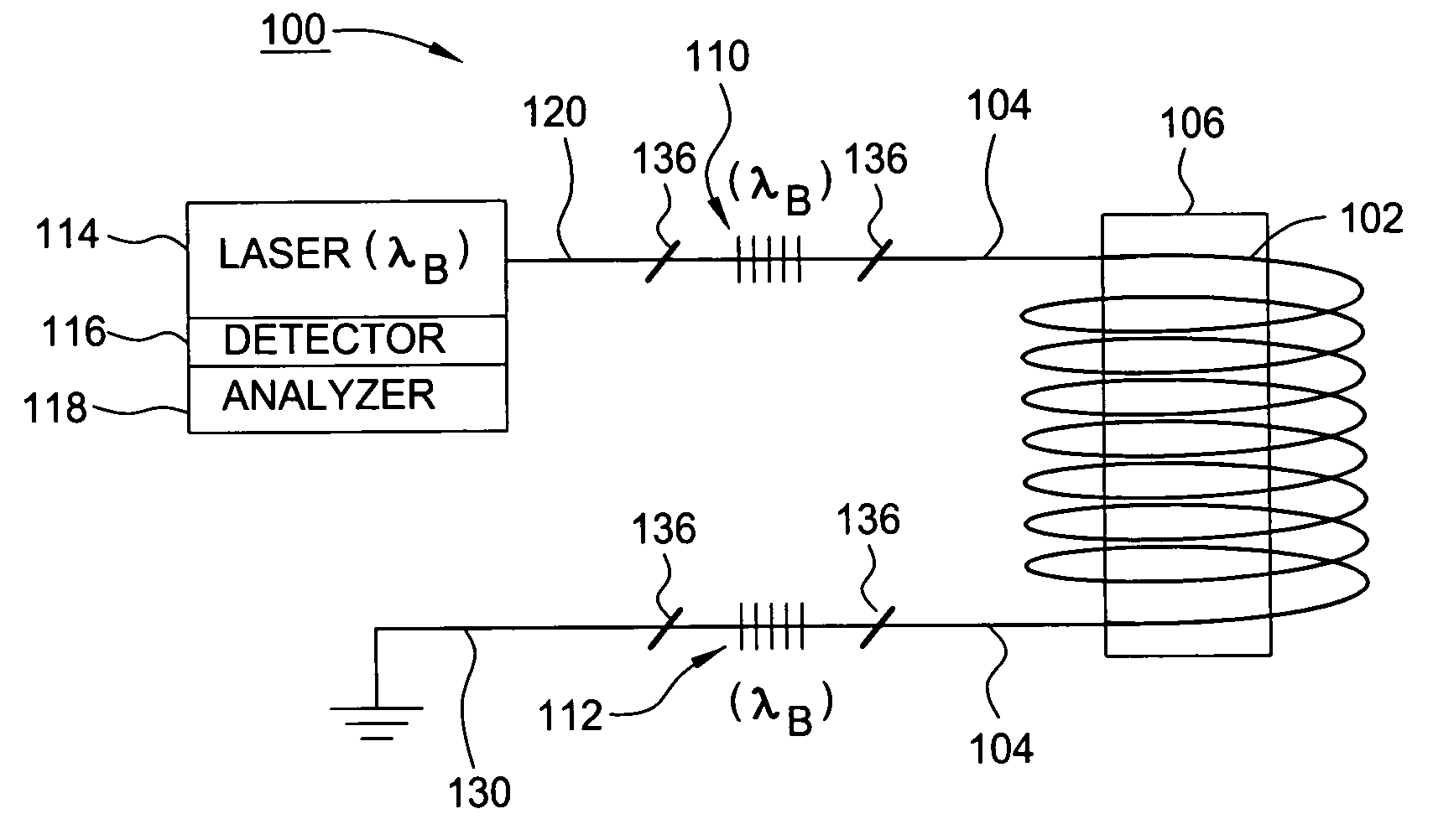
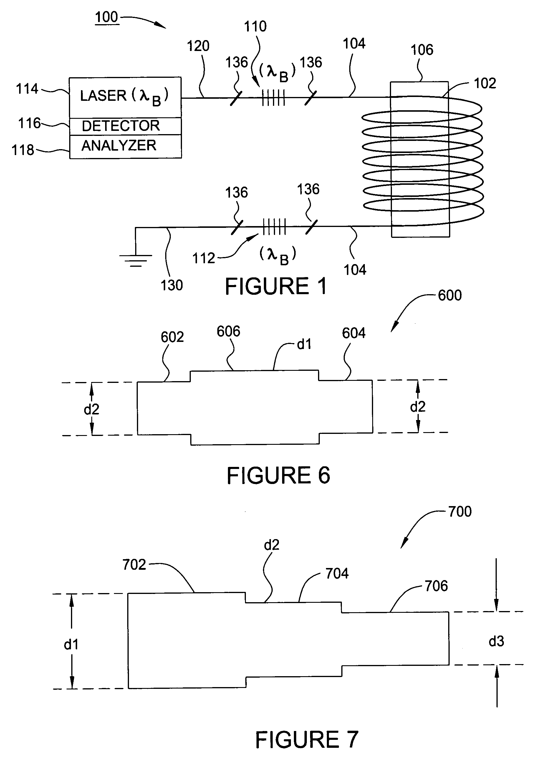
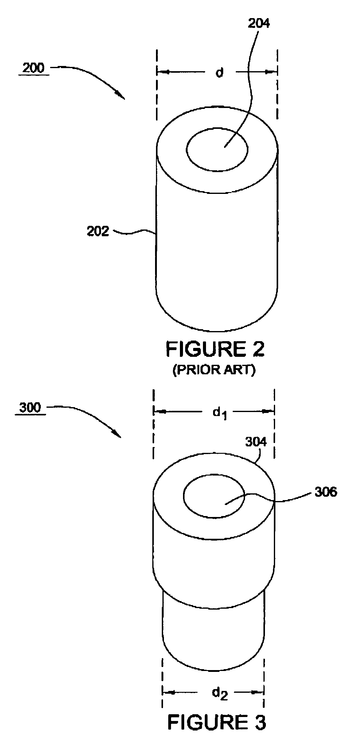
[0021]The principles of the present invention provide for optical waveguide interferometric hydrophones having Bragg gratings between optical waveguide sections that are wound on mandrels having at least two different outer diameters. Some embodiments of the present invention include bored mandrels, where the bores physically protect the Bragg gratings from both physical damage and from excessive strain. The different outer diameters enable accurate control of the length between the gratings which, in turn, allows accurate positioning of the Bragg gratings.

[0022]To facilitate understanding, embodiments of the present invention are described below with reference to acoustic sensors (hydrophones) as a specific, but not limiting application example. However, it should be appreciated that the apparatus and techniques described herein may be used to control the length between (and facilitate precise placement of) reflective elements of any type of interferometric sensor device.

[0023]FIG....


PUM

PropertyMeasurementUnit
diameteraaaaaaaaaa
lengthaaaaaaaaaa
diametersaaaaaaaaaa

Abstract

A method and apparatus for reducing the difficulty of controlling the length of a section of optical waveguide wrapped around a mandrel separating Bragg gratings forming an interferometric sensor are provided. The section of optical waveguide may be wrapped on a mandrel having at least two different outer diameters. The mandrel may also include one or more bores for receiving and protecting the Bragg gratings.

Description

BACKGROUND OF THE INVENTION[0001]1. Field of the Invention[0002]Embodiments of the present invention relate to optical waveguide interferometric-based hydrophones and, more specifically, to mandrels used in such hydrophones.[0003]2. Description of the Related Art[0004]A Bragg grating is an optical element that is reflective to light having wavelengths within a narrow bandwidth that is centered at a wavelength that is referred to as the Bragg wavelength. Bragg gratings are usually formed by photo-induced periodic modulation of the refractive index of an optical waveguide's core. A pair of Bragg gratings having a common Bragg wavelength and separated by a length of waveguide (e.g. a coiled fiber or coil) can form an interferometer that may be interrogated by sending light of the same Bragg wavelength through the interferometer. Reflections of light from the (partially-transmissive) Bragg gratings are sent back to optical detection equipment through the waveguide. By assessing the phas...

Claims


Application Information

Patent Timeline
Patent Type & Authority Patents(United States)
IPC IPC(8): G02B6/34G01B9/02G01D5/26G01H9/00G01L1/24G01V1/18G02B6/00H04R1/44H04R23/00
CPCG01D5/35316G01V1/186H04R1/44G02B6/29356G01D5/268G01L1/246H04R23/008
Inventor WOO, DANIEL MING KWONG
Owner WEATHERFORD TECH HLDG LLC
Why Eureka
Try Eureka