Maintaining data access during failure of a controller

a controller and data access technology, applied in memory systems, redundant hardware error correction, instruments, etc., can solve problems such as insufficient to solve the problem, not everything can be caught, and the feature of a failing controller sending a stop message to other controllers is often disabled

Inactive Publication Date: 2006-10-03
LINKEDIN
View PDF15 Cites 12 Cited by
  • Summary
  • Abstract
  • Description
  • Claims
  • Application Information

AI Technical Summary

Benefits of technology

[0020]The storage subsystem may be a Fibre Channel Arbitrated Loop system and the multiple controllers may be host bus adapters. During the defined method, interrupts may be disabled. A flag may be set in a host bus adapter during the saving of internal state information to prevent overlapping saves of internal state information in that adapter. The adapter may save information relating to an interface chip.

Problems solved by technology

This results in multiple controller dumps at the time of the error that are often essential to solve a problem.
The feature where a failing controller sends a stop message to other controllers is often disabled in the field because the systems are high availability systems.
Therefore, when problems happen, only one controller dump is taken which often is not sufficient to solve the problem.
Most problems should be detected and fixed during test procedures, but obviously, not everything can be caught.
The problem with the above approach is that either all the controllers reset and there is a loss of access to storage devices during the simultaneous reset of the controllers, or only the defective controller resets and there is insufficient information to solve the defect.

Method used


Image

  • Maintaining data access during failure of a controller
  • Maintaining data access during failure of a controller
  • Maintaining data access during failure of a controller

Examples


first embodiment

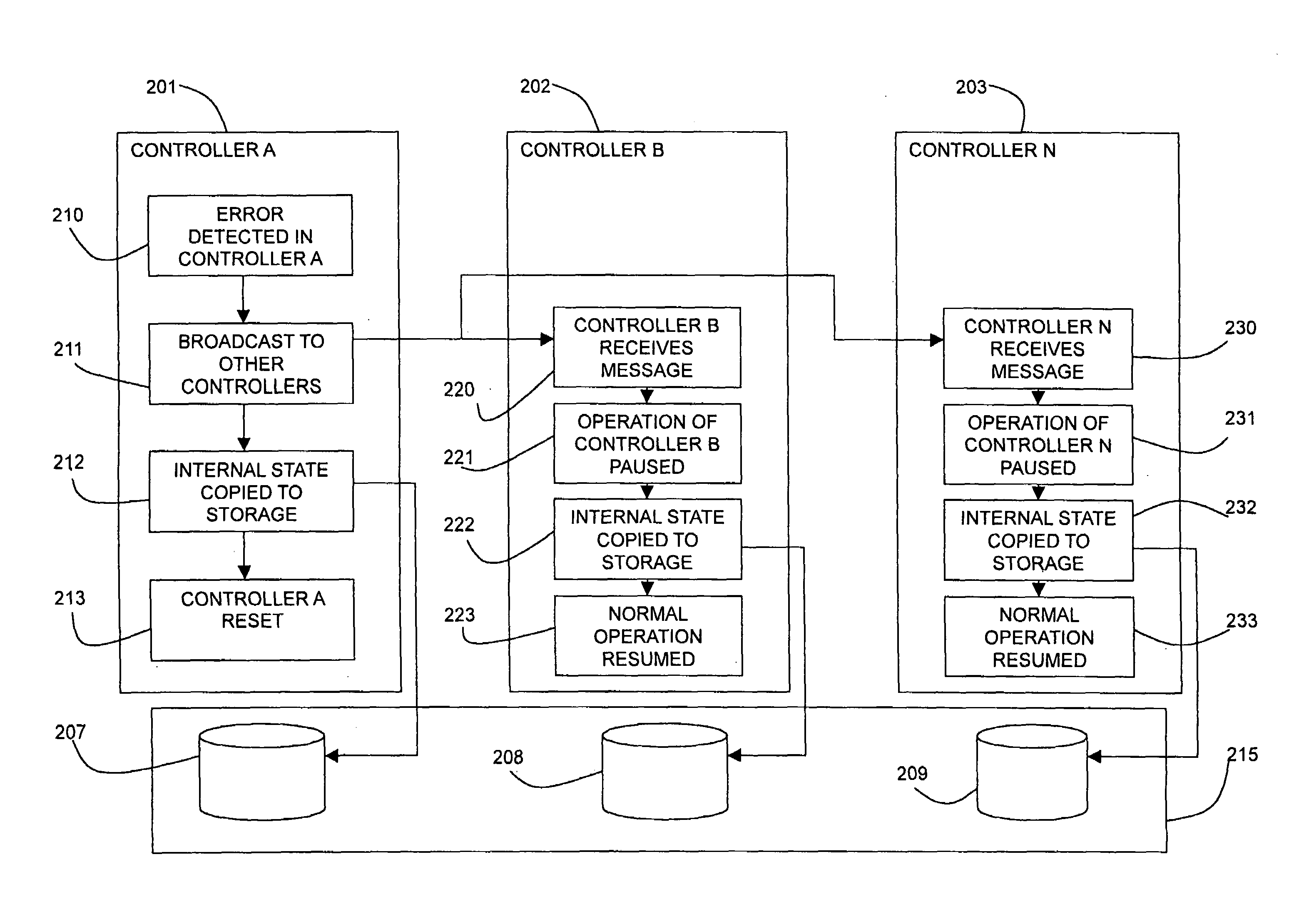
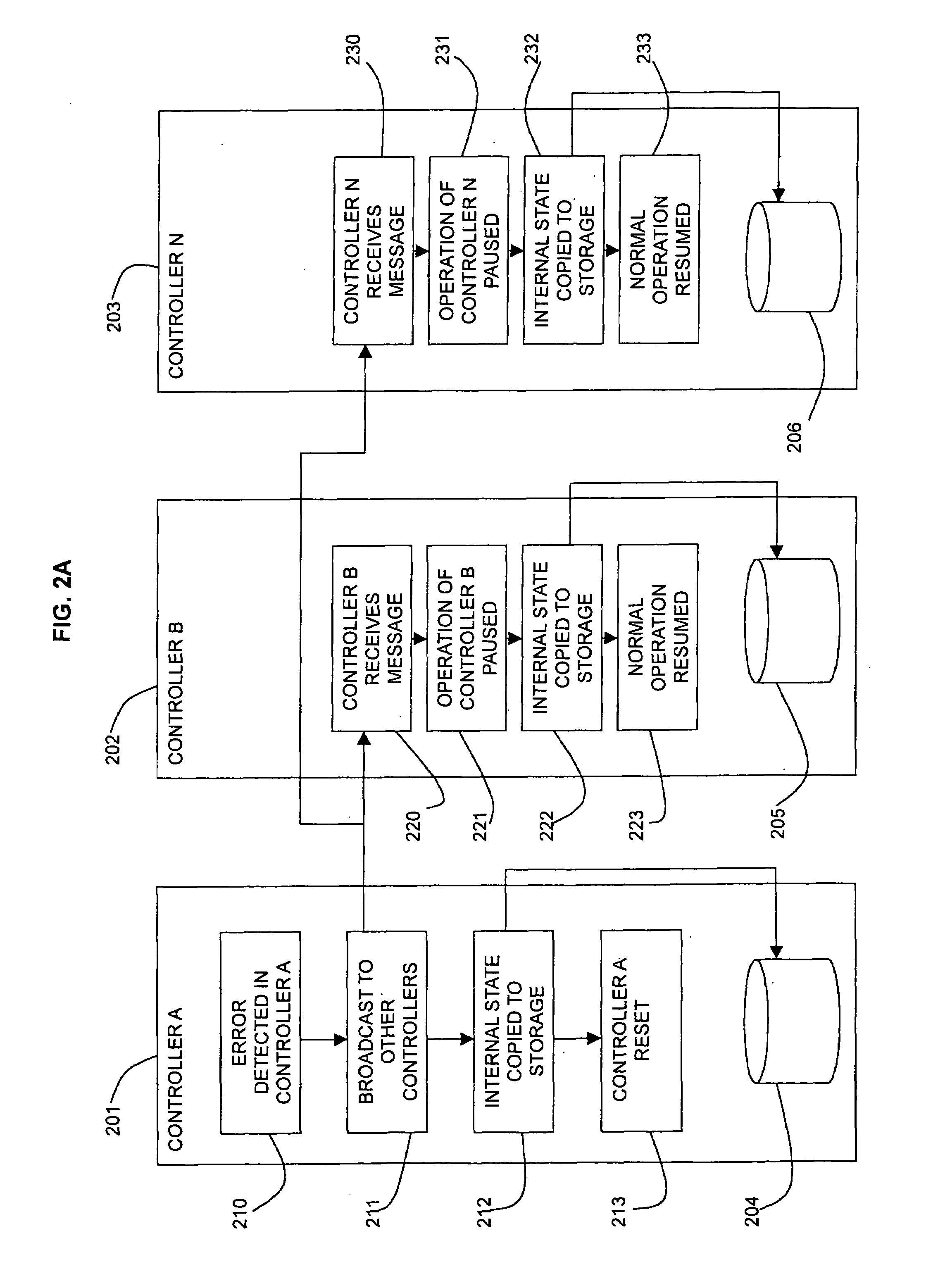
[0034]FIG. 2A shows the described method as carried out in multiple controllers 201, 202, 203 labelled as controller A, controller B and controller N. The method steps taken in each controller 201, 202, 203 are shown in the form of flow diagrams.

[0035]One of the multiple controllers, controller A 201, detects an error 210 in that controller 201. Controller A 201 sends an instruction, which may be by broadcasting 211 a message, to the other controllers 202, 203. Controller A 201 then copies 212 its internal state to a storage buffer 204 in controller A 201. Controller A 201 then resets itself 213. During the resetting process, controller A 201 is out of action and cannot accept commands to access the storage device array.

[0036]In controller B 202, the message broadcast from controller A 201 is received 220. The operation of controller B 202 is paused 221 for sufficient time for the internal state of controller B 202 to be copied 222 to a storage buffer 205 in controller B 202. Normal...

second embodiment

[0039]FIG. 2B shows the described method. In this embodiment, controller A 201 saves or dumps the copy of its internal state data to a predetermined storage location 207 in the storage device array 215. Similarly, the other controllers B 202 and N 203 save their internal state data to predetermined storage locations 208, 209 in the storage device array 215.

[0040]The dumped information that has been saved to predetermined locations 207, 208, 209 in the storage device array 215 can be retrieved as required by controller A 201 which detected the error 210.

third embodiment

[0041]FIG. 2C shows the described method in which the controller which detected the error, controller A 201, broadcasts 211 a message to the other controllers 202, 203 requesting that they send their internal state information to the broadcasting controller, controller A 201. The controller A 201 receives and stores the internal state information from all the controllers 201, 202, 203 in a storage buffer 214 in controller A 201.

[0042]This third embodiment allows controller A 201 to assemble a complete set of synchronised dumps for all the controllers 201, 202, 203 in the subsystem and store them in a single location.

[0043]Controller A 201 can save the complete set of synchronised dumps for all the controllers 201, 202, 203 to a storage location in the storage device array 215.

[0044]In another embodiment of the described method, a controller may detect the loss of one of the other controllers in the storage subsystem. When such a loss is detected by the detecting controller, it pause...


PUM


Abstract

A method for maintaining data access during failure of a controller in a multiple controller storage subsystem (103) is provided. The storage subsystem (103) has an array of data storage devices (109) and more than one controller (104, 105) for managing the data storage. The method comprises a first controller (201) saving its internal state information (212) and, optionally, resetting itself (213). One or more of the other controllers (202, 203) carry out the steps of pausing operation of the controller (221, 231), saving internal state information of the controller at the time of pausing (222, 232), and continuing operation of the controller (223, 233). The one or more other controllers (202, 203) may pause operation and save their internal state information when they receive a message broadcast (220, 230) from the first controller (201) which has detected an error.

Description

FIELD OF THE INVENTION[0001]This invention relates to the field of storage subsystems and in particular to methods and apparatus which provide shared access to common storage devices by multiple storage controllers within a storage subsystem.BACKGROUND OF THE INVENTION[0002]Modern mass storage subsystems must provide increasing storage capacity to meet user demands from host computer system applications. Various storage device configurations are known and used to meet the demand for higher storage capacity while maintaining or enhancing reliability of the mass storage subsystem.[0003]One of the storage configurations that meets demands for increased capacity and reliability is the use of multiple smaller storage modules which are configured to permit redundancy of stored data to ensure data integrity in case of failures. In such redundant subsystems, recovery from many types of failure can be automated within the storage subsystem itself due to the use of data redundancy. An example...

Claims


Application Information

Patent Timeline
Patent Type & Authority Patents(United States)
IPC IPC(8): G06F11/00G06F11/07G06F11/20
CPCG06F11/0727G06F11/0778G06F11/0784G06F11/2089
Inventor ASHMORE, PAULFAIRHURST, MATTHEW JOHNFRANCIS, MICHAEL HUWNICHOLSON, ROBERT BRUCEWALSH, SIMONWOOD, BARRY JOHN
Owner LINKEDIN
Why Eureka
Try Eureka