System for constructing log structures

a construction system and log structure technology, applied in the direction of dovetail-like connections, structural elements, rod connections, etc., can solve the problems of difficult to provide the corner connection of logs at an intersecting corner, limited lifespan of caulking, and difficulty in constructing such log structures

Inactive Publication Date: 2006-10-10
POINTBLANK DESIGN
View PDF41 Cites 41 Cited by
  • Summary
  • Abstract
  • Description
  • Claims
  • Application Information

AI Technical Summary

Benefits of technology

[0023]Alternatively, the anti-rotate coupling device may have a coupling sleeve coupled to the through-bolt, a locking pin having ends projecting outwardly from the sleeve, and a generally horizontal lock bore provided in the wall and intersecting the bolt cavity, wherein the outwardly projecting ends of the locking pin are adapted to engage the lock bore to prevent rotation of the coupling sleeve.

Problems solved by technology

However, constructing such log structures can present a number of difficulties.
For example, it can be difficult to provide corner connection of logs at an intersecting corner that is strong and weather tight, both at initial installation and after the log walls have settled over time.
However, the structural elements themselves leave seams through which the weather could penetrate.
Caulking could be provided for weather-proofing, but caulking has a limited lifespan, and could work loose during natural settling and shrinkage of the logs.
Alternatively, gaskets could be provided between the mating faces of the dovetails, but gaskets can be relatively costly and time-consuming to install.
However, by providing the mortise adjacent the intersecting region, rather than within the intersecting region, the locking member is engaged only at its outer ends by the mortise, which may limit the strength and support provided by the locking member.
Furthermore, Schilbe does not address the natural settling of the logs that takes place over time.
However, such a tight fit would also inhibit vertical movement of the logs relative to the locking member, which could result in gaps forming between the logs along the height of the walls at the intersecting corner.
However, providing such access may be difficult, and may require, for example, fairly large openings cut into the lower sides of the walls.
This butt joint is fairly complex and may be time consuming to assemble.
Furthermore, the simultaneous alignment of the passageways and the lobes within the recesses may be difficult to achieve.
Since no structural joint element engages the logs in a transverse direction, it may be difficult to ensure that the logs connected by this joint are in fact locked to inhibit longitudinal movement.
Furthermore, since the gasket strips are installed prior to fixing the logs together, the strips may be damaged during positioning and assembly of the logs.
Using nails driven into the end grain of the logs may not, however, provide a secure joint because the nails may work loose as the fibers of the wood separate.
Furthermore, shrinkage of the logs over time may compromise the strength of the support structure.
However, at either side of the logs, the profile provides a generally horizontal seam portion which could collect moisture and cause associated wood preservation difficulties.
However, no provision is made for installing seals along the seam between adjacent logs, at a point along the seam between the outer horizontal edges.
Accordingly, the weather-proofing of the interface between adjacent logs may be compromised, particularly as the logs shrink and settle over time.
However, no adjustable fastening means is provided for drawing the post and log ends snugly together.

Method used


Image

  • System for constructing log structures
  • System for constructing log structures
  • System for constructing log structures

Examples


Embodiment Construction

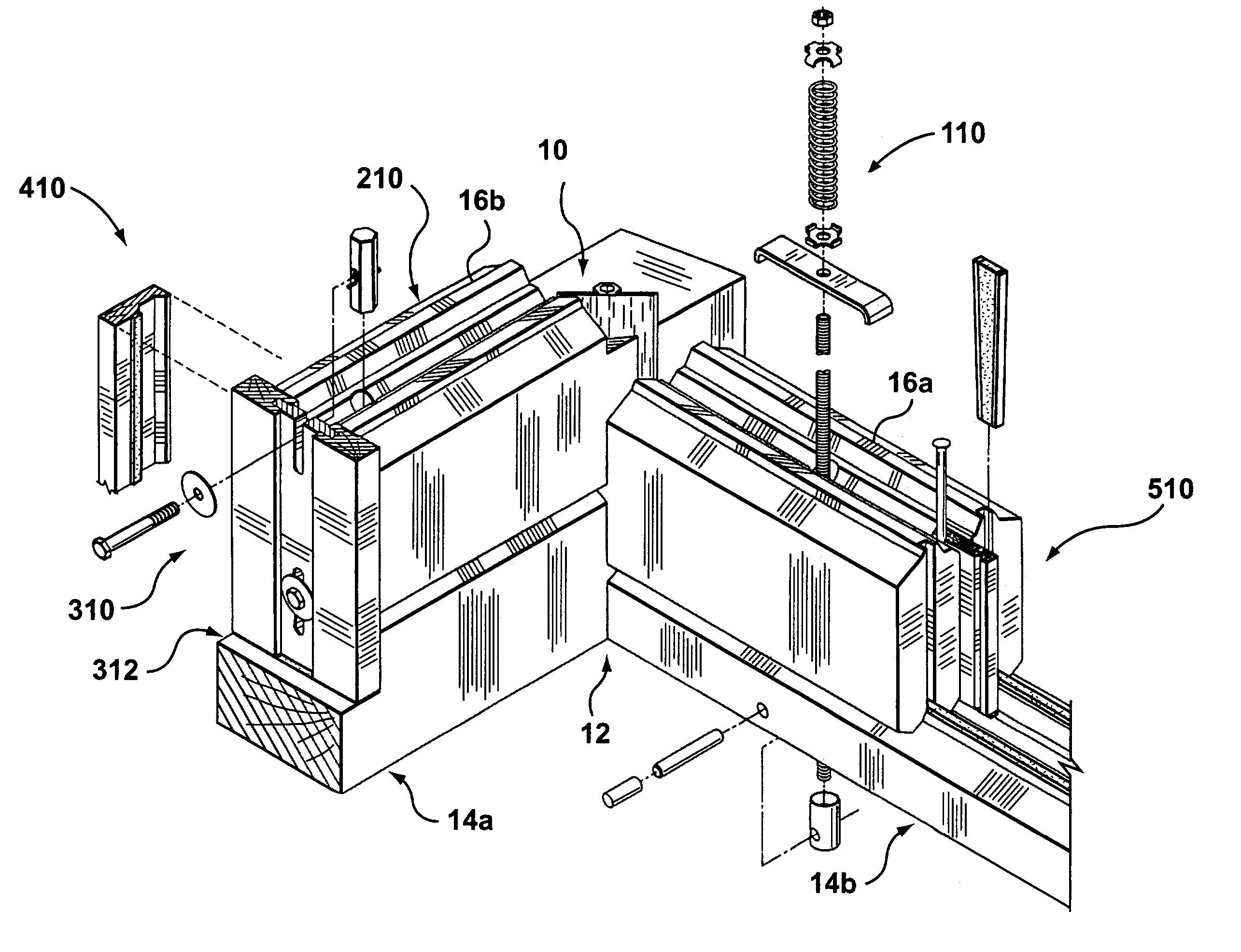
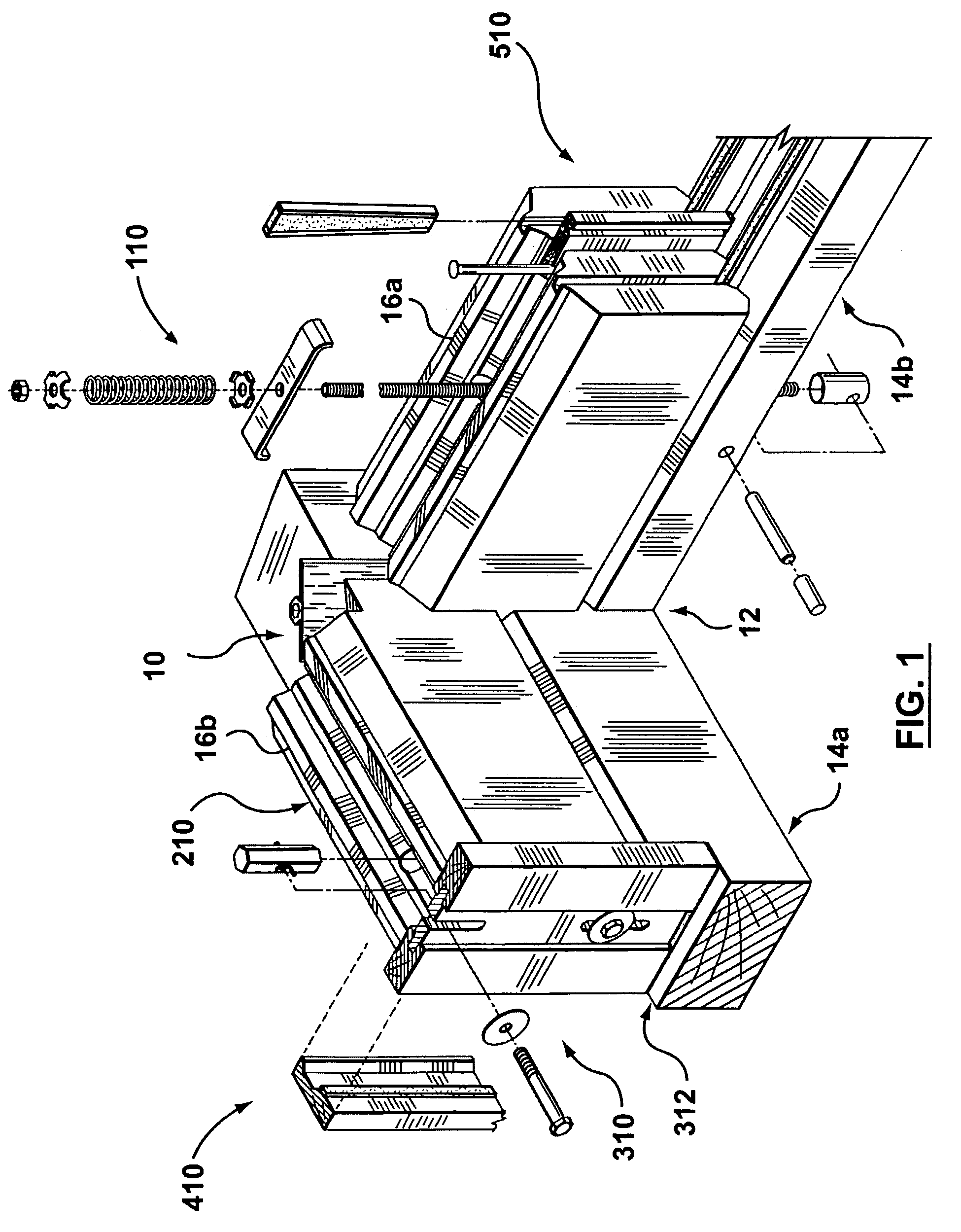
[0097]A corner connection structure according to the present invention is shown generally at 10 in FIG. 1. The corner connection structure 10 is provided at a corner 12 where walls 14a and 14b intersect. The walls 14a and 14b form part of a building such as, for example, but not limited to, a home or cabin.

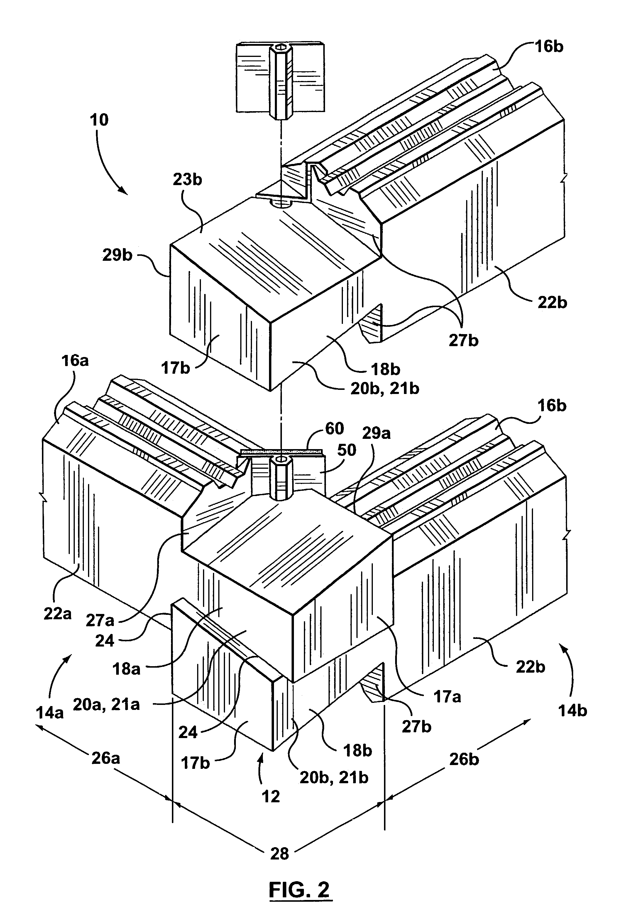
[0098]Referring to FIG. 2, the walls 14a and 14b are constructed of generally horizontally extending logs 16a and 16b, respectively. The walls 14a and 14b are nonparallel, intersecting each other at the corner 12. In the embodiment illustrated, the walls 14a and 14b intersect at approximately 90°. However, the angle of intersection at corner 12 could be any angle, and it is to be appreciated that the corner connection structure 10 could be used on walls having any angle of intersection, and also on walls meeting at a T-intersection.

[0099]The logs 16a and 16b of the walls 14a and 14b have ends 17a and 17b which are proximate the corner 12. Adjacent the ends17a and 17b, the logs 16a...


PUM


Abstract

A system for constructing log structures includes a corner connection structure, a through-bolt clamping apparatus, an opening support structure, a butt joint connection structure, a log profile, and an exterior casing structure. The corner connection structure has logs with overlap portions shaped so that the overlap portions of the logs of a first wall overlap and alternately interlace the overlap portions of the logs of a second wall. A generally vertical slot extends through the overlap portions of the logs, and at least one spline is provided in the slot. The through-bolt clamping apparatus has a through-bolt extending along the height of the wall, a lower clamp arm coupled to the through-bolt and the bottom of the intersecting walls, and an upper clamp arm coupled to the through bolt and the top of the intersecting walls.

Description

FIELD OF THE INVENTION[0001]This invention relates to construction systems for constructing log structures such as houses, cabins, and the likeBACKGROUND OF THE INVENTION[0002]Homes or cabins built of logs are often considered desirable for their aesthetics. However, constructing such log structures can present a number of difficulties. For example, it can be difficult to provide corner connection of logs at an intersecting corner that is strong and weather tight, both at initial installation and after the log walls have settled over time.[0003]A known corner connection structure is disclosed in U.S. Pat. No. 5,020,289 (Wrightman). The corner connection of Wrightman provides a dovetail joint between the intersecting logs, and a pair of splines having a ‘figure-8’ cross-sectional profile. However, the structural elements themselves leave seams through which the weather could penetrate. Caulking could be provided for weather-proofing, but caulking has a limited lifespan, and could wor...

Claims


Application Information

Patent Timeline
Patent Type & Authority Patents(United States)
IPC IPC(8): E04B1/10E04B2/70E04C3/12
CPCE04B2/702E04C3/12Y10T403/4685Y10T403/4688Y10T403/4645Y10T403/3933Y10T403/4682Y10T403/4602Y10T403/73Y10T403/4697Y10T403/4681F16B2200/40F16B2200/403F16B2200/406F16B7/0486F16B2200/30F16B2200/67
Inventor CLARKE, GREGORY A.
Owner POINTBLANK DESIGN
Why Eureka
Try Eureka