Thrust control valve

a technology of thrust control valve and thrust control, which is applied in the direction of vessel construction, marine propulsion, aircraft navigation control, etc., can solve the problems of reducing the accuracy of guiding flying objects, the inability to control the atmosphere satisfactorily, and the inability to achieve orbital control (diversion) of the same, so as to reduce the consumption of propulsion gas, reduce the load, and reduce the flow rate of propulsion gas

Active Publication Date: 2006-10-10
KAWASAKI HEAVY IND LTD
View PDF16 Cites 3 Cited by
  • Summary
  • Abstract
  • Description
  • Claims
  • Application Information

AI Technical Summary

Benefits of technology

[0012]Accordingly, it is an object of the present invention to provide a thrust control valve having a plug which is capable of reducing load loaded by a propulsion gas on the plug, of reduc

Problems solved by technology

The attitude of a flying object that flies at high altitudes in the atmosphere cannot satisfactorily be controlled and the orbital control (diversion) of the same cannot satisfact

Method used


Image

  • Thrust control valve
  • Thrust control valve
  • Thrust control valve

Examples


Embodiment Construction

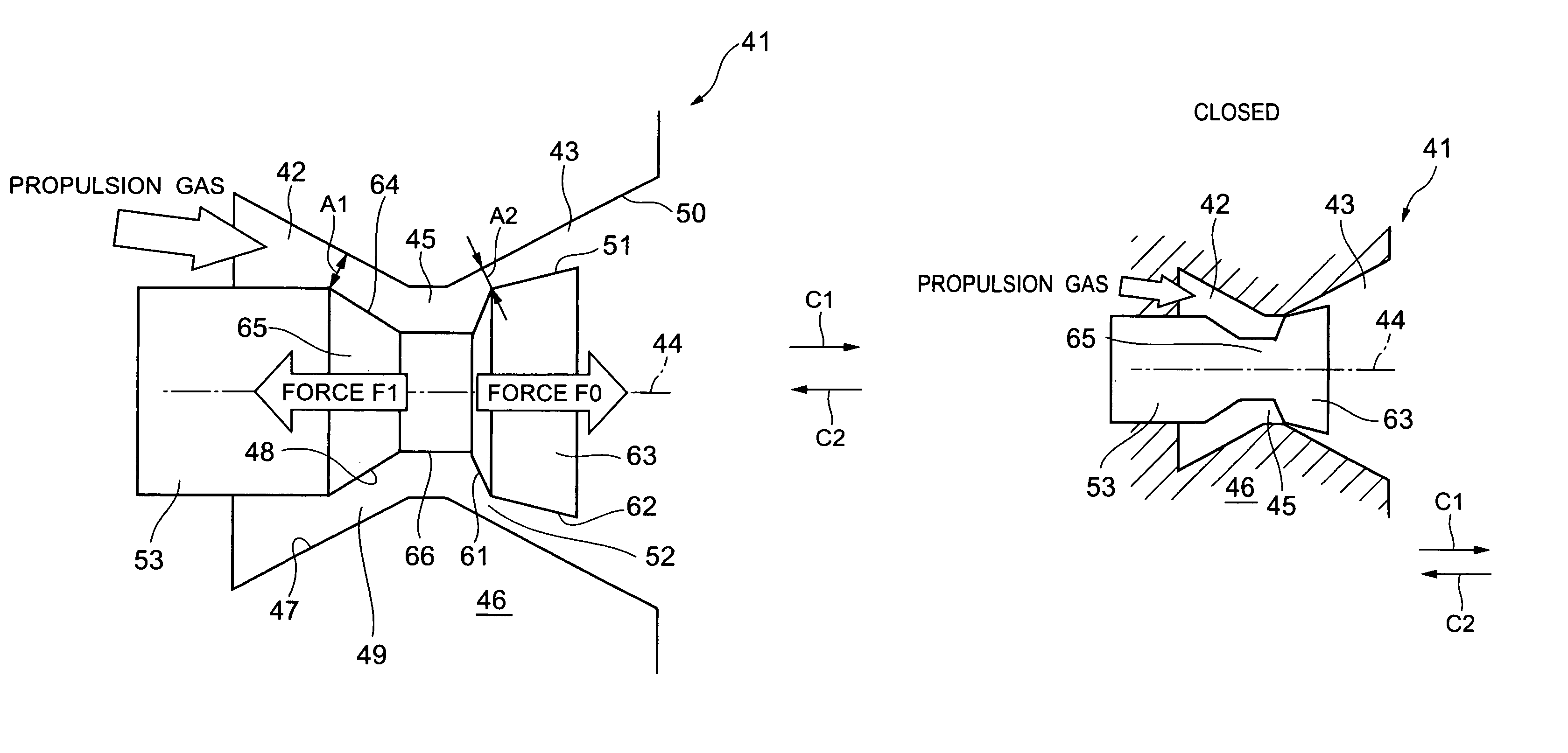
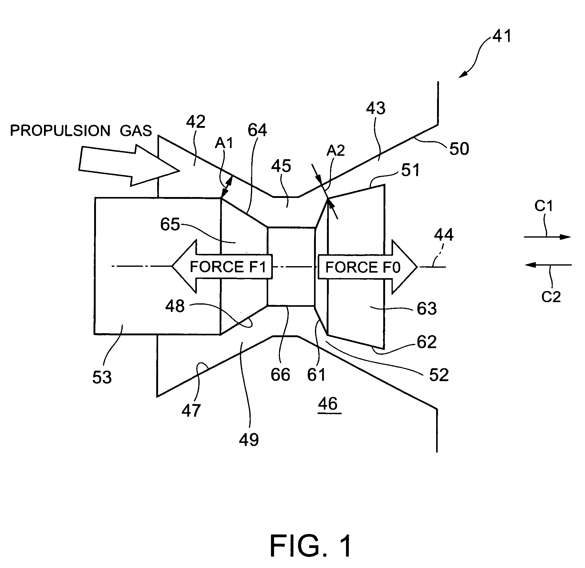
[0037]The thrust control valve 41 in a preferred embodiment according to the present invention is mounted on a flying object to control the thrust (propulsion) of a secondary propulsion engine, such as a thruster for the control of the orbit and attitude of the flying object, and the speed of the flying object.

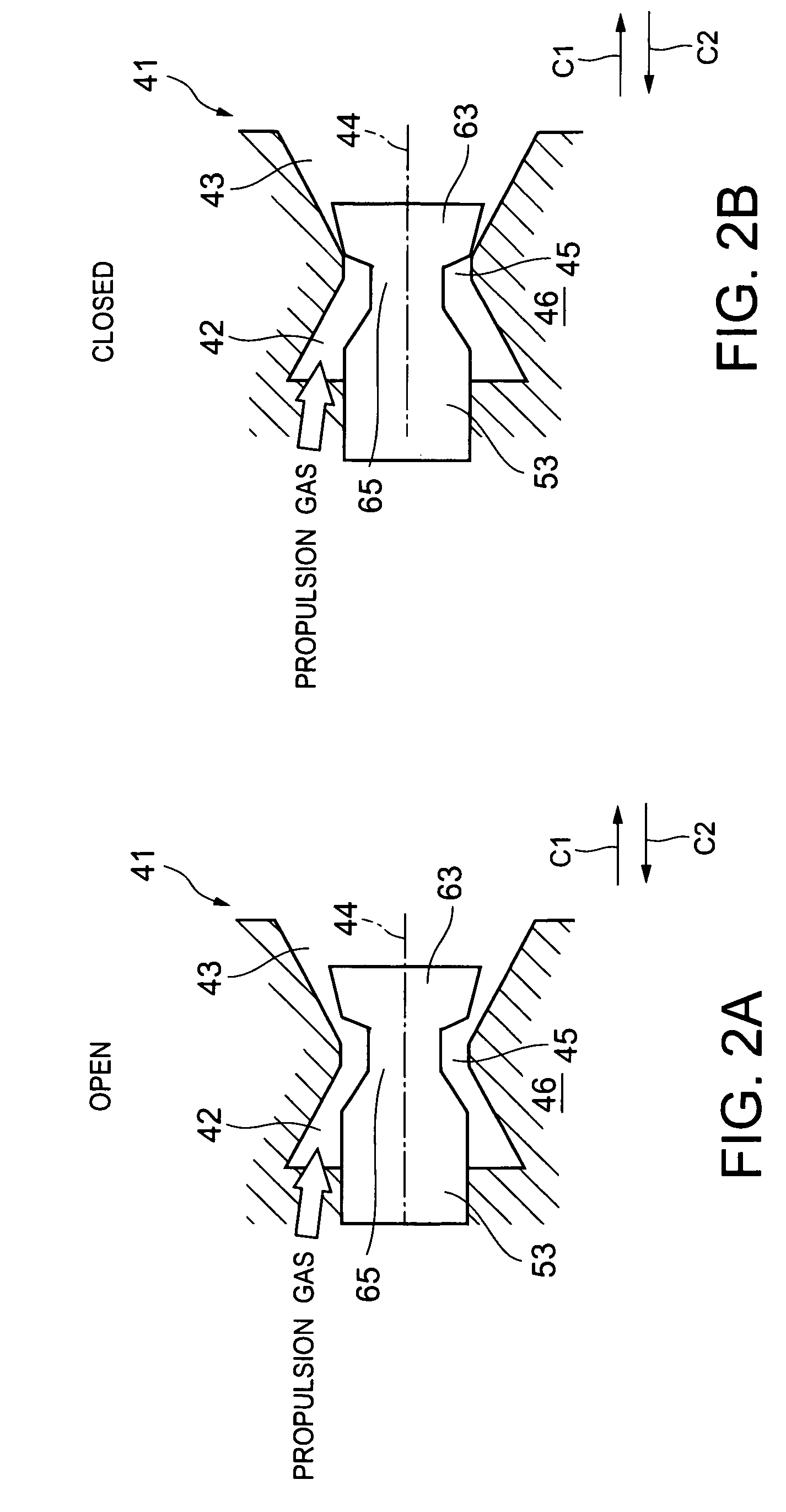
[0038]The thrust control valve 41 includes a nozzle 46 provided with a gas supply chamber 42 in which a propulsion gas is supplied, a gas jetting chamber 43 through which the propulsion gas is jetted, and a connecting passage 45 coaxial with the gas supply chamber 42 and the gas jetting chamber 43 and having an axis 44 in common with the gas supply chamber 42 and the gas jetting chamber 43. The thrust control valve 41 also includes a plug 53 axially movable in the directions of the arrows C1 and C2 along the axis 44 in the gas supply chamber 42, the connecting passage 45 and the gas jetting chamber 43.

[0039]The plug 53 moves in the direction of either the arrow C1 or the arrow...


PUM


Abstract

A thrust control valve includes a nozzle having a gas supply chamber, a gas jetting chamber and a connecting passage therebetween. The nozzle has an upstream inner surface defining the gas supply chamber and a downstream inner surface defining the gas jetting chamber. The valve also includes a plug axially movably inserted into the gas supply chamber, the connecting passage and the gas jetting chamber. The plug has an upstream outer surface facing the upstream inner surface to define an upstream passage and a downstream outer surface facing the downstream inner surface to define a downstream passage. The plug can control thrust by simultaneously changing sectional areas of the upstream and downstream passages by an axial movement of the plug.

Description

BACKGROUND OF THE INVENTION[0001]1. Technical Field[0002]The present invention relates to a constitution of a thrust control valve for controlling the thrust (propulsion) of a secondary propulsion engine, such as a thruster for controlling the orbit and attitude of a flying object, and the speed of the flying object.[0003]2. Description of the Related Art[0004]The attitude of a flying object that flies at high altitudes in the atmosphere cannot satisfactorily be controlled and the orbital control (diversion) of the same cannot satisfactorily achieved only by a control effort generated by a control wing. Therefore, the flying object is provided with a thruster that jets a high-pressure propulsion gas supplied from a chamber containing a propellant. The thruster is provided with a thrust control valve called a propellant valve for controlling the thrust generated by jetting the propulsion gas.[0005]FIGS. 6A and 6B are typical views of a conventional pintle thrust control valve 1 in an...

Claims


Application Information

Patent Timeline
IPC IPC(8): F02K1/00F02K9/86F42B10/66
CPCF02K9/86
Inventor KATO, HIROSHITAKAHASHI, TATSUOTANAKA, HIDEAKINISHIKAWA, TATSUYA
Owner KAWASAKI HEAVY IND LTD
Why Eureka
Try Eureka