Load detecting vehicle seat assembly

a technology for vehicle seats and components, applied in the directions of instruments, force/torque/work measurement apparatus, transportation and packaging, etc., can solve the problems of increased cost and/or unusable (scrap) components, and achieve the effect of reducing the input of vehicle body dimensional variation and significant cost savings

Inactive Publication Date: 2006-10-10
LEAR CORP
View PDF20 Cites 3 Cited by
  • Summary
  • Abstract
  • Description
  • Claims
  • Application Information

AI Technical Summary

Benefits of technology

[0007]The present invention provides a number of advantages. For example, the present invention provides a load sensing vehicle seat assembly that satisfies strain gage mounting requirements using a mounting plate disposed between the strain gage and vehicle seating component. Use of a smaller component to satisfy the strain gage flatness mounting requirement may result in significant cost savings relative to manufacturing larger and / or more complex components with the desired flatness, such as the cushion frame or seat adjuster for example. Positioning of the strain gage assembly between the seat adjuster and cushion frame reduces vehicle body dimensional variation input to the strain gage compared to mounting the strain gage below the seat adjuster, between the seat adjuster and the floor, for example.

Problems solved by technology

Due to the size and / or complexity of the components that may have surfaces suitable for mounting the strain gage, such as the cushion frame, seat adjuster, and / or seat riser, for example, manufacturing such components with the desired flatness tolerance for accurate load indication of the strain gage(s) is difficult and may result in increased cost and / or unusable (scrap) components.

Method used


Image

  • Load detecting vehicle seat assembly
  • Load detecting vehicle seat assembly
  • Load detecting vehicle seat assembly

Examples


Embodiment Construction

)

[0012]As those of ordinary skill in the art will understand, various features of the present invention as illustrated and described with reference to any one of the Figures may be combined with features illustrated in one or more other Figures to produce embodiments of the present invention that are not explicitly illustrated or described. The combinations of features illustrated provide representative embodiments for typical applications. However, various combinations and modifications of the features consistent with the teachings of the present invention may be desired for particular applications or implementations.

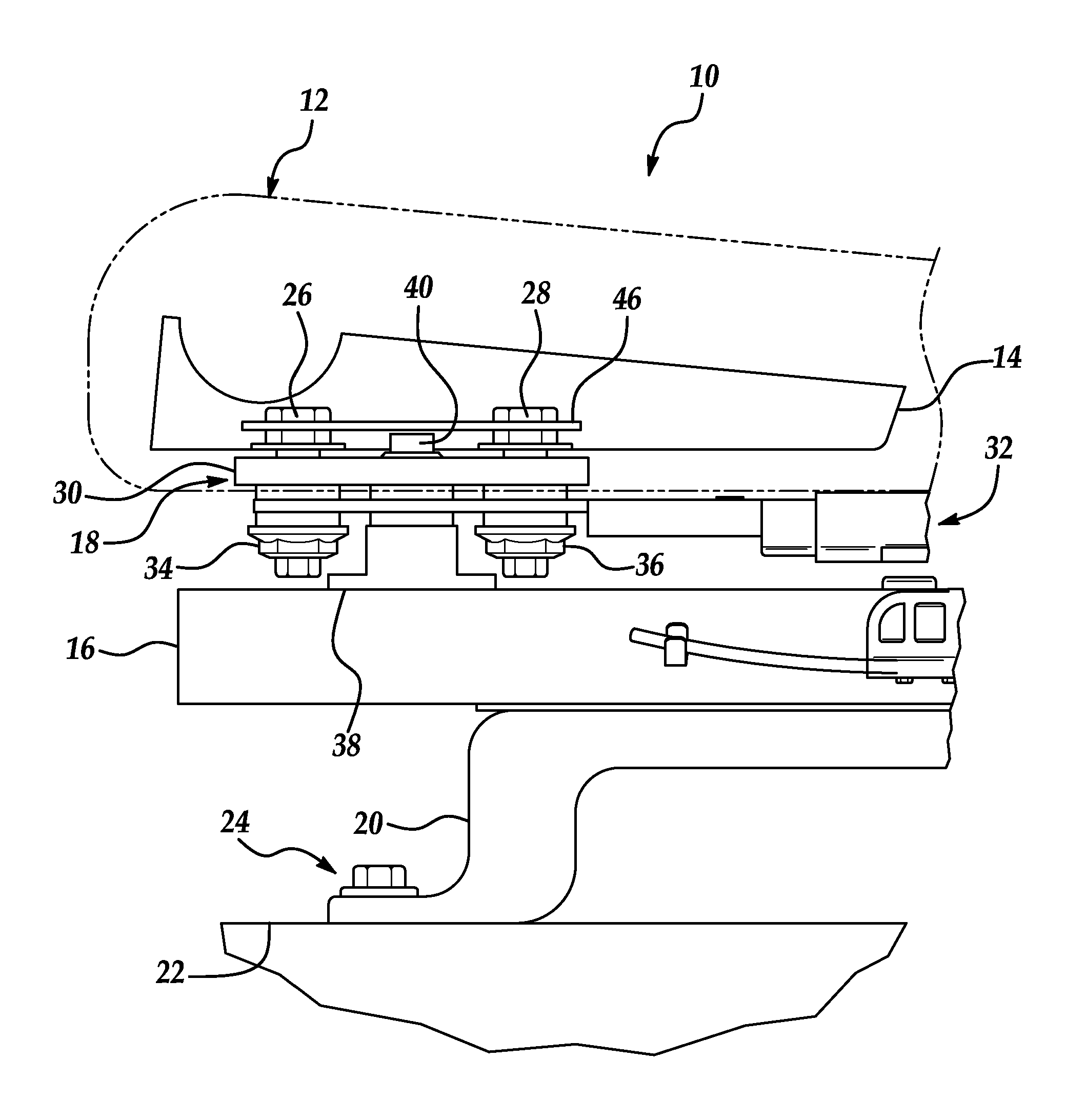
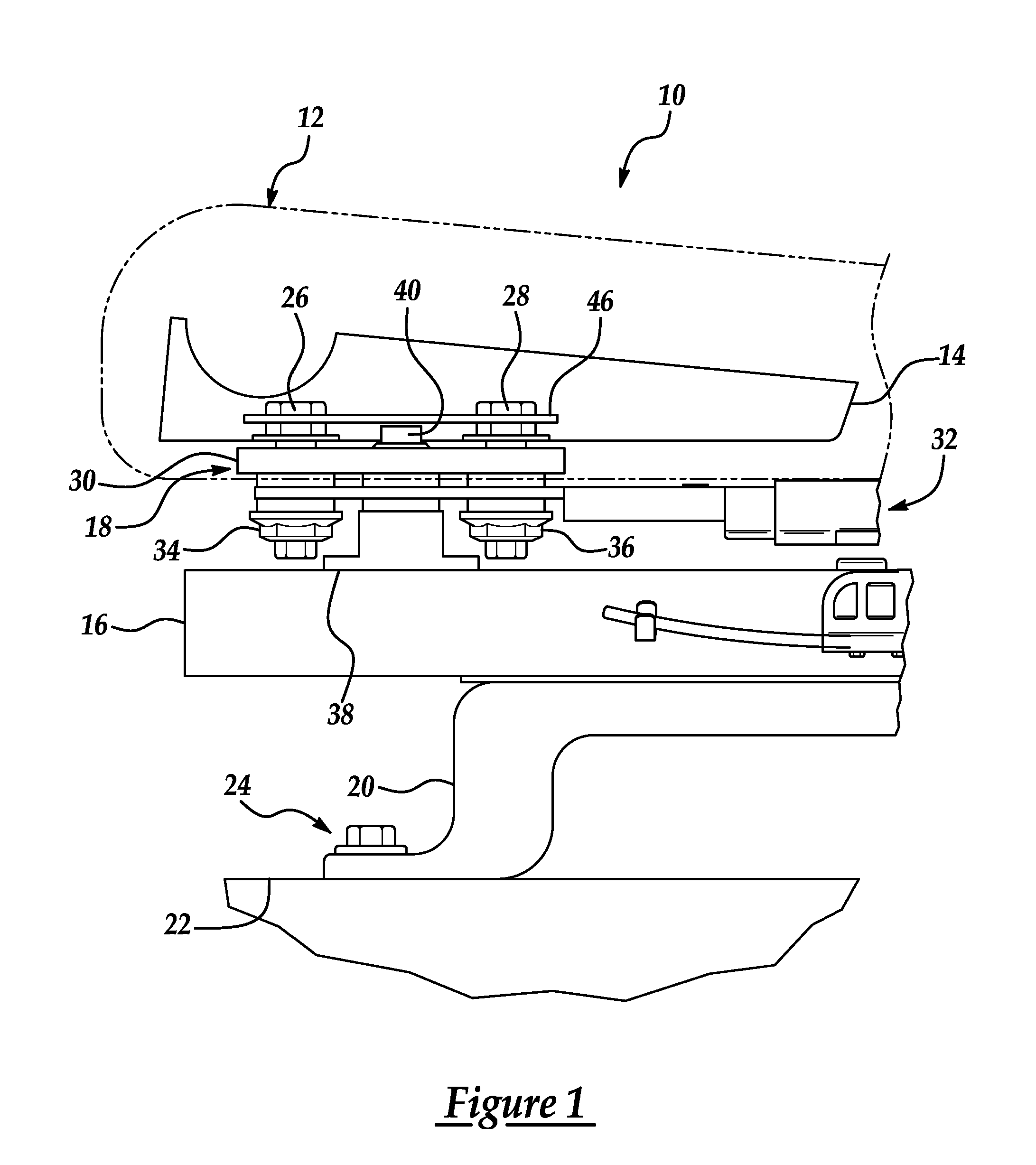
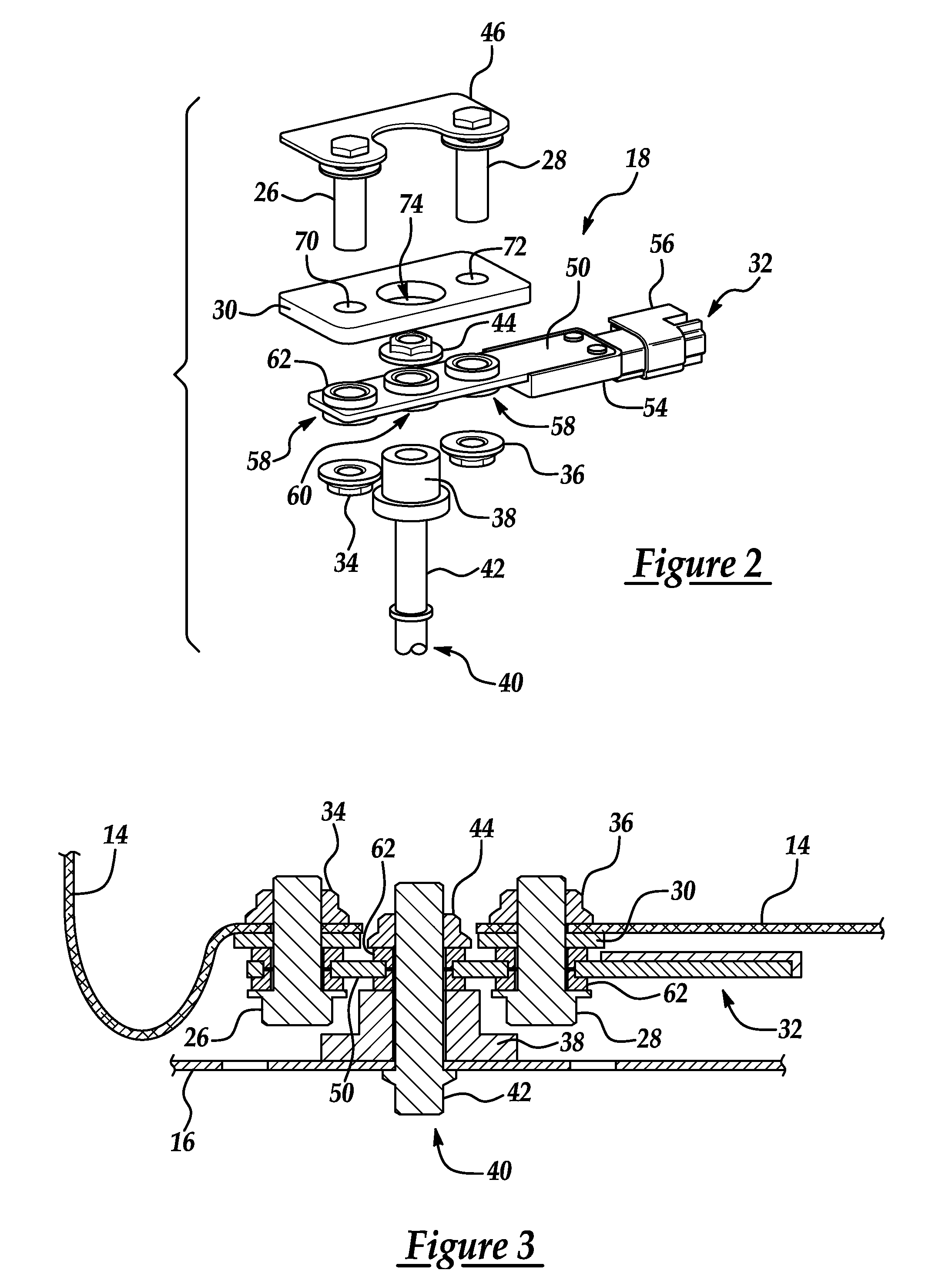
[0013]Referring now to FIG. 1, a load sensing vehicle seat assembly according to one embodiment of the present invention is shown. Assembly 10 includes a seat cushion 12 mounted on a cushion frame 14. Cushion frame 14 is secured to a conventional sliding seat adjuster 16 via strain gage assembly 18. Depending upon the particular application and implementation, a strain...


PUM

PropertyMeasurementUnit
surface flatness toleranceaaaaaaaaaa
flatnessaaaaaaaaaa
thicknessaaaaaaaaaa

Abstract

A load detecting vehicle seat assembly includes a discrete strain gage mounting plate having a specified flatness to produce desired strain gage performance. The strain gage mounting plate is disposed between a strain gage and a vehicle seat component, such as a cushion frame, so that vehicle seat loading is transferred to the strain gage through the mounting plate. The strain gage may be mounted with a central portion secured to a lower vehicle seat component and outward portions secured to an upper vehicle seat component such that only the outward portions of the strain gage contact the strain gage mounting plate, which has a controlled flatness tolerance to produce desired strain gage performance.

Description

BACKGROUND OF THE INVENTION[0001]1. Field of the Invention[0002]The present invention relates to load detecting vehicle seat assemblies.[0003]2. Background Art[0004]A number of vehicle manufacturers have implemented vehicle seat load sensing systems, particularly for use in determining whether and / or how forcefully to deploy one or more airbags in an accident. One strategy for detecting the weight or load placed on a vehicle seat is to use one or more strain gages associated with a particular seat or position on the seat. The strain gage or gages may be positioned so that a load (such as created by an occupant) on the vehicle seat deflects an associated surface of the strain gage with the deflection or strain used to generate a corresponding signal indicative of the load. For repeatable measurements with a desired accuracy, strain gages may require a specific flatness tolerance for the mounting surface of the seat component. Due to the size and / or complexity of the components that m...

Claims


Application Information

Patent Timeline
Patent Type & Authority Patents(United States)
IPC IPC(8): G01L1/22
CPCB60N2/002B60N2/0732G01L1/044
Inventor RYBAK, STEPHEN RPAWLITZ, DAVID PGLINKA, PAULMODRESKI, MICHAEL P
Owner LEAR CORP
Why Eureka
Try Eureka