Quartz glass tool for heat treatment of silicon wafer and process for producing the same

a glass tool and silicon wafer technology, applied in the field of tools for silicon wafer heat treatment, can solve the problems of inability to ensure the purity of silicon wafers, acute concaves and convexes based on the opening of microcracks in the grooved surface, and the inability to completely clean the grooved surface, etc., to achieve the effect of reducing the change in size and being easy to produ

Inactive Publication Date: 2011-08-16
SHIN ETABU QUARTZ PRODS
View PDF5 Cites 1 Cited by
  • Summary
  • Abstract
  • Description
  • Claims
  • Application Information

AI Technical Summary

Benefits of technology

[0006]The inventors of the present invention have earnestly made studies under such circumstances and found that a quartz glass tool free from attachment of particles, e.g., particles of glass dust due to collapse of acute irregularities based on minute concaves and convexes or opening of microcracks or particles of various transition metal element foreign matters generated from a diamond blade or the like, capable of maintaining a high degree of cleanness during use for a long time, having finer concaves and convexes in a grooved surface of a wafer mount member ground with a diamond blade and having a reduced change in size even during cleaning with fluoric acid can be obtained by making the grooved surface transparent, setting the surface roughness of the entire grooved surface to 0.03 to 0.3 μm in center-line average roughness (Ra) and 0.2 to 3.0 μm in maximum roughness (Rmax) and by setting the rates of change in the center line average roughness (Ra) and the maximum roughness (Rmax) after etching with a 5% hydrogen fluoride aqueous solution for 24 hours to 50% or less. The inventors also found that the above-described quartz glass tool can be easily produced by grinding the portion to be grooved of the wafer mount member of the quartz glass tool with a diamond blade of a coarse particle size, again grinding the grooved portion with a diamond blade of a small particle size, and making the ground portion transparent by fire finishing with oxyhydrogen gas flame.
[0007]That is, an object of the present invention is to provide a quartz glass tool for silicon wafer heat treatment having a transparent grooved surface, free from attachment of particles of glass dust due to collapse of acute irregularities based on minute concaves and convexes or opening of microcracks or particles of a transition metal element foreign matter due to a diamond blade or the like, having a reduced change in size even during cleaning with fluoric acid and capable of maintaining a high degree of cleanness during use for a long time.
[0013]The quartz glass tool for silicon wafer heat treatment according to the present invention is free from attachment of particles of glass dust due to collapse of acute irregularities based on minute concaves and convexes or opening of microcracks or particles of a transition metal element foreign matter due to a diamond blade or the like, has a reduced change in size even during cleaning with fluoric acid and can be used for a long time. This quartz glass tool can be easily produced by performing grinding with a diamond blade of a coarse particle size, again performing grinding with a diamond blade of a small particle size, and performing fire finishing on the grooved surface.

Problems solved by technology

With working on quartz glass with a diamond blade, however, there is a problem that since quartz glass is a brittle material, minute concaves and convexes and microcracks are generated in the worked surface to cause damage to a silicon wafer, or various transition metal element foreign matters derived from a bonding material on the diamond blade are attached to and remain on or in the minute concaves and convexes and microcracks and are molten and diffused at the time of a heat treatment on a silicon wafer to contaminate the silicon wafer.
Cleaning by lightly etching with a fluoric acid solution after cutting with a diamond blade has therefore been practiced, with the result that the grooved surface is not completely cleaned; various transition metal element foreign matters remain to cause contaminations on silicon wafers.
With further etching with a fluoric acid, a problem has arisen that minute concaves and convexes based on opening of microcracks in the grooved surface are made acute such as to damage a silicon wafer.
In particular, in recent years, the degree of integration of semiconductor devices has been increased and devices such as flush memories seriously badly influenced by impurities have been developed, so that the desired purity with respect to silicon wafers cannot be ensured as long as the above-described quartz glass tool is used.
Also, with the method in patent document 2, there has been a problem such as a silicon wafer contamination problem due to remaining of the trace of a grindstone and attachment of particles of a foreign matter, glass dust or the like to the trace of the grindstone.Patent document 1: Japanese Patent Laid-Open No. 11-349338Patent document 2: Japanese Patent Laid-Open No. 2000

Method used


Image

  • Quartz glass tool for heat treatment of silicon wafer and process for producing the same
  • Quartz glass tool for heat treatment of silicon wafer and process for producing the same
  • Quartz glass tool for heat treatment of silicon wafer and process for producing the same

Examples


example 1

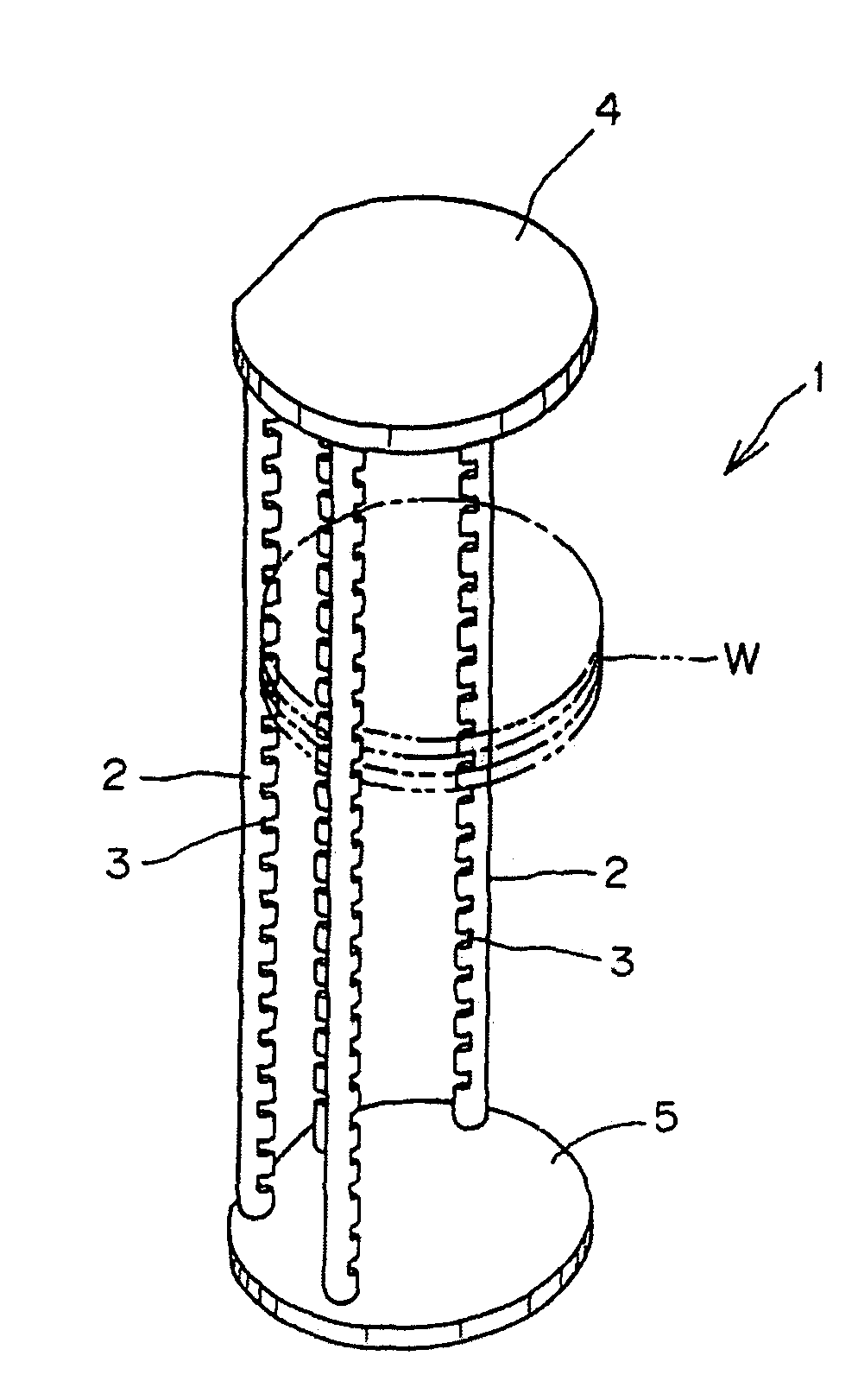
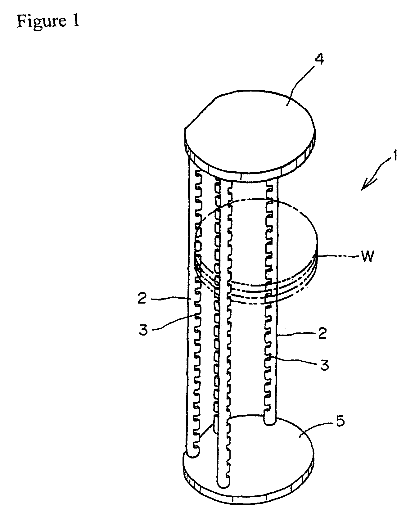
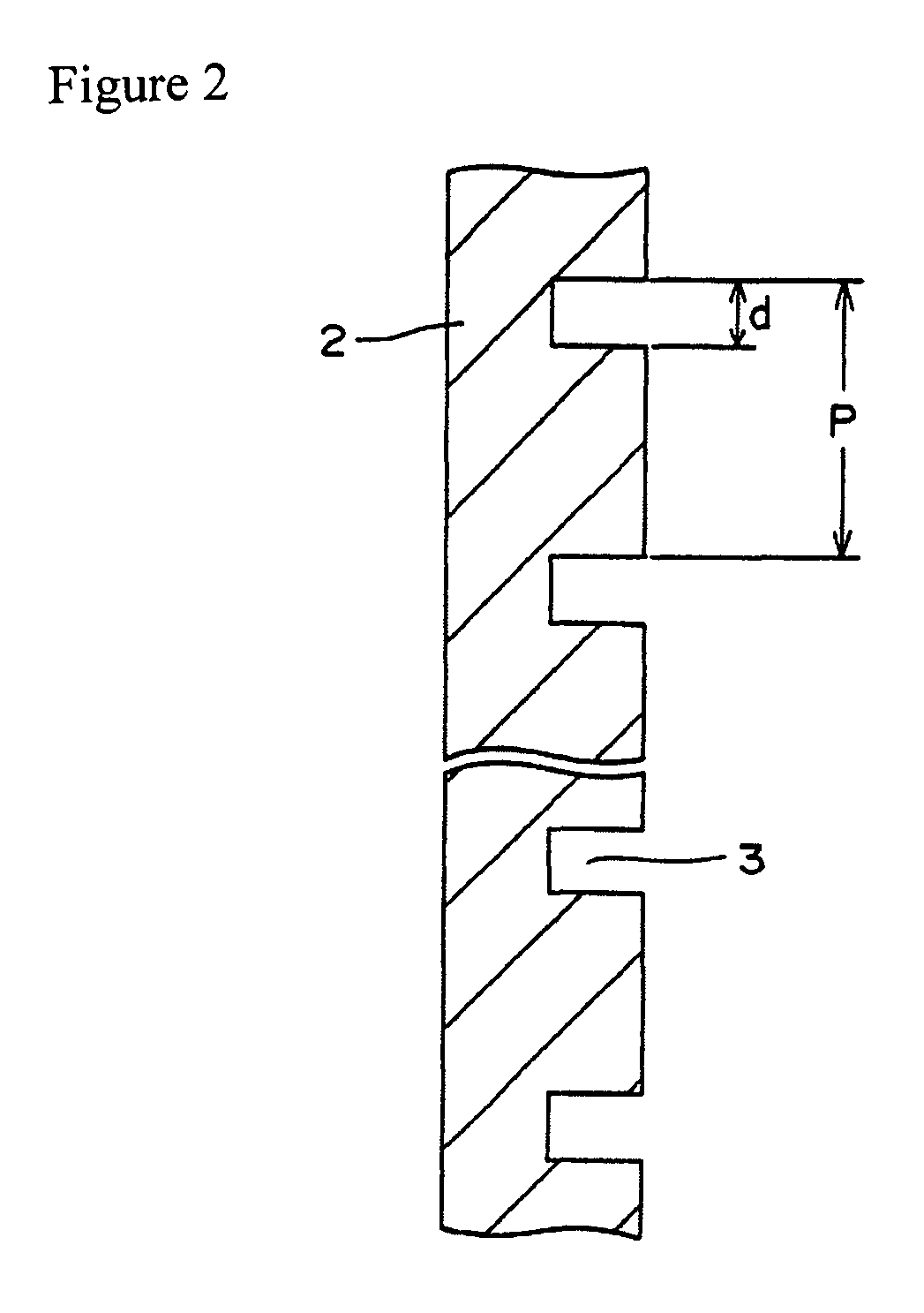
[0023]A solid rod having a diameter of 12 mm was ground by using a #325 diamond blade at a peripheral velocity of 800 m / min. and at a feed rate of 100 mm / min. with a groove depth of 6 mm, a groove width of 3.4 mm and a groove pitch of 3.5 mm. The grooved rod obtained was again ground by using a #1000 diamond blade with a side surface machining allowance of 0.075 mm and a bottom surface machining allowance of 0.07 mm, as shown in FIG. 3, and fire-finished with a gas burner to be made transparent. Four wafer mount members with grooves having a groove width of 3.55 mm and a pitch width of 3.6 mm were made in this way. The wafer mount members were cleaned with 5% fluoric acid aqueous solution for 10 minutes and thereafter assembled in a wafer port 1 shown in FIG. 1 by being welded to a quartz glass top plate 4 and a base plate 5. Table 1 shows the surface roughness of the grooved surface of the wafer mount member. The center-line average roughness (Ra) and the center-line maximum roughn...

example 2

[0024]A grooved wafer mount member with grooves having a groove width of 3.55 mm and a pitch width of 3.6 mm was made by grinding a solid rod having a diameter of 12 mm with a #325 diamond blade at a peripheral velocity of 800 m / min. and at a feed rate of 100 mm / min., with a groove depth of 6 mm, a groove width of 3.4 mm and a groove pitch of 3.5 mm, again grounding the rod with a #1000 diamond blade, with a side surface machining allowance of 0.075 mm and a bottom surface machining allowance of 0.07 mm, and making the grooves transparent by fire finishing with a gas burner, as was that in Example 1. To check size stability of the wafer mount member with grooves under fluoric acid cleaning, the groove bottom and groove wall surfaces were examined for Ra and Rmax when the wafer mount member was immersed in 5% fluoric acid cleaning solution for 1 to 24 hours. Table 3 shows the results of this examination, which are also indicated by symbol ⋄ in FIGS. 4 to 7. Table 3 shows average valu...


PUM

PropertyMeasurementUnit
particle sizeaaaaaaaaaa
Raaaaaaaaaaa
Raaaaaaaaaaa

Abstract

To provide a quartz glass tool, for silicon wafer heat treatment, having a transparent grooving face, which is free from the deposition of particles of a transition metal element foreign material derived from glass dust or diamond blade produced by breakdown of acute irregularities based on opening of very small concaves and convexes and microcracks, causes no significant change in dimension also in cleaning with hydrofluoric acid, and can maintain a high degree of cleanness even after use of a long period of time, and to provide a process for producing the same. A quartz glass tool for silicon wafer heat treatment, comprising a wafer mounting member having a grooving face formed by machining, characterized in that the whole grooving face of the wafer mounting member is transparent, the surface roughness is 0.03 to 0.3 μm in terms of center line average roughness (Ra) and 0.2 to 3.0 μm in terms of maximum roughness (Rmax), and a change in center line average roughness and maximum roughness after etching with a 5% aqueous hydrogen fluoride solution for 24 hr is not more than 50%. A process for producing a quartz glass tool for silicon wafer heat treatment, comprising roughly machining a wafer mounting member with a diamond blade having a rough particle size, conducting remachining with a diamond blade having a finer particle size than the above diamond blade, and then subjecting the inside of the groove to firing finishing.

Description

TECHNICAL FIELD[0001]The present invention relates to a tool for silicon wafer heat treatment having a transparent grooved surface and a process for producing the tool. More particularly, the present invention relates to a quartz glass tool for silicon wafer heat treatment having, as a grooved surface of a wafer mount member provided in the quartz glass tool, a transparent grooved surface with a reduced amount of materials such as particles with which a silicon wafer is contaminated, and to a process for producing the tool.BACKGROUND ART[0002]Quartz glass tools having comparatively high heat resistance and high purity have been used for transporting silicon wafers and holding silicon wafers in heating furnaces. An example of such quartz glass tools is a tool for use in a vertical furnace, such as shown in FIG. 1, in which (four) wafer mount members 2 having grooved portions 3 are welded to a top plate 4 and to a base plate 5. It is necessary to form grooves in the wafer mount member...

Claims


Application Information

Patent Timeline
Patent Type & Authority Patents(United States)
IPC IPC(8): B28D5/00B24B1/00
CPCH01L21/67303H01L21/67306H01L21/02
Inventor TSURUZOE, JUNICHIOKOSHI, SHINICHIYAMASAKI, KUNIHIRO
Owner SHIN ETABU QUARTZ PRODS
Why Eureka
Try Eureka