Percussion hammer bit retainer apparatus

Active Publication Date: 2006-10-10
ATLAS COPCO CONSTR MINING TECHN USA +1
View PDF13 Cites 42 Cited by
  • Summary
  • Abstract
  • Description
  • Claims
  • Application Information

AI Technical Summary

Benefits of technology

[0020]The first embodiment of the bit retention apparatus of the current invention is referred to as a dual sleeve retention (“DSR”) system. The DSR system provides protection against the described extreme conditions and occurrences. The DSR system not only provides both a primary, or inner, retainer sleeve, and a secondary, or outer, retainer sleeve. The inner retainer sleeve remains connected to, or catches, the bit when the bit breaks. The outer protective sleeve provides protection against the side walls of the hole to prevent washing of the inner retainer sleeve. In this manner, a broken bit is retained, and can be retrieved while being protected from the extreme conditions found down-hole.
[0021]As described above, numerous devices for the general purpose of retaining and recovering broken bits exist, but none of these systems provide the extra protection of the DSR system as described by the current invention. The bit retention apparatus provides a system where extreme over-pull and unthreading of broken bit is greatly reduced. The bit retention apparatus of the current invention fits, or can be adapted to fit, virtually any downhole percussion drill bit.
[0027]Once the bit retention apparatus is in place, the bit can be used normally in its operation. While the drill string is lowered into the hole, the bit is in a non-operating mode, extended, fully open and off bottom. As the bit contacts the bottom of the well bore, the bit will then travel inside the chuck and lower end of the percussion tool so as to set the internal working parts of the drill in the working mode. In this cycling mode of the tool, energy is delivered to the bit via an internal moving piston. The energy is then transmitted into the rock / soil formation in order to commence actual drilling operations. Once the bit retention device is in place, it allows the bit to travel and function without any hindrance.
[0029]Therefore, it is the object of this invention to position a retaining mechanism in the larger head section (below the shank area) of the bit in order to retain the bit head after most failures occur. It is also the object of this invention to minimize the chance of the bit head from being dropped during the trip out of the hole.

Problems solved by technology

Retrieving the bit head from the bottom of the hole is expensive and difficult.

Method used


Image

  • Percussion hammer bit retainer apparatus
  • Percussion hammer bit retainer apparatus
  • Percussion hammer bit retainer apparatus

Examples


Embodiment Construction

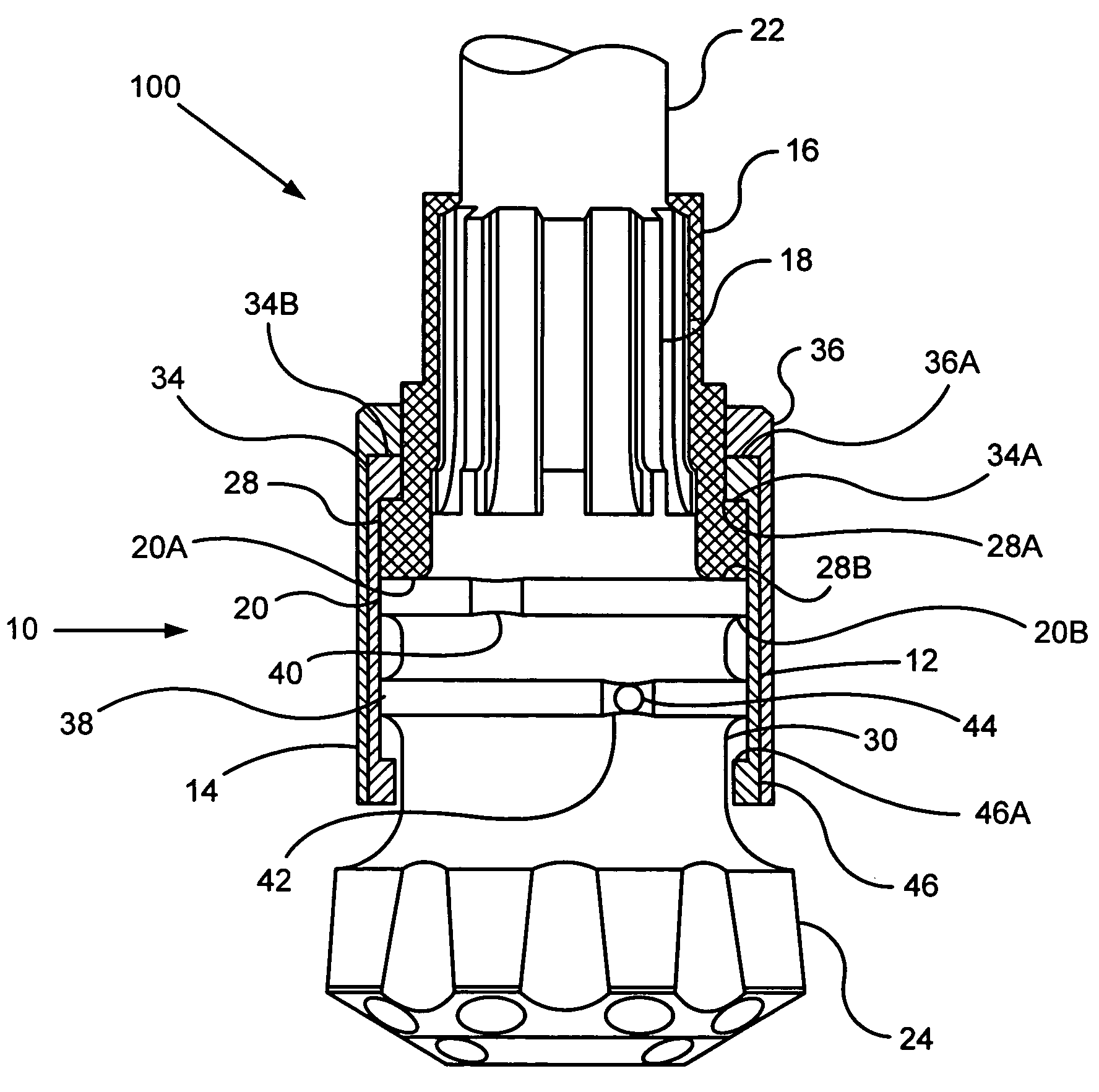
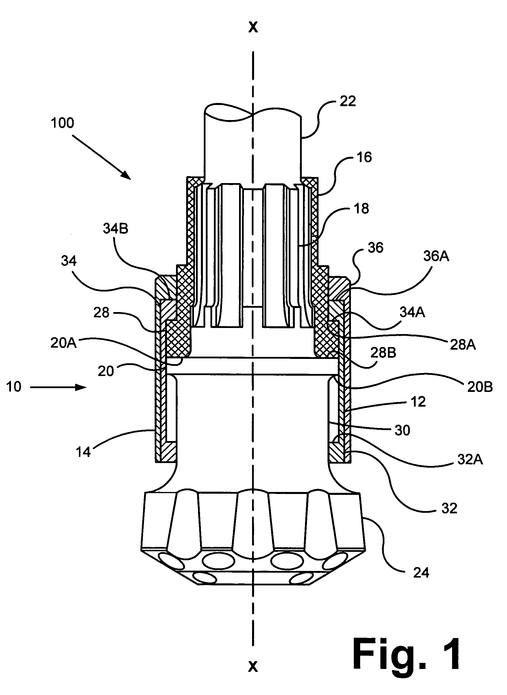
[0038]FIG. 1. is a partial sectional view of a first embodiment of the bit 100 and the retainer assembly 10. It illustrates orientation of the inner retainer sleeve 12 and outer protective sleeve 14 in relation to the bit 100. The anticipated breakage area of the bit shaft 22 lies between the bit splines 18 and the retaining ring 20. Therefore, in order to retain the bit cutting end 24 if shankage of the bit shaft 22 occurs, the inner retainer sleeve 12 is placed about the bit shaft 22. (As used herein, “downward” means in the direction toward the bit cutting end 24 along the bit shaft 22 and central axis X—X, while “upward” means in the direction away from the bit cutting end 24 along the bit shaft 22 and central axis X—X.)

[0039]The inner retainer sleeve 12 is a hollow, generally cylindrically shaped device. Retention is accomplished because the inner retainer sleeve 12 has a first collar 32 and a second collar 34 at its opposite ends. The collars 32&34 extend inwardly from the inn...


PUM


Abstract

A bit retention apparatus for the use of retrieving the hammer bit in cases of shankage. The apparatus incorporates a dual sleeve design that fits over the chuck and the extended head section of the hammer bit. The first, “inner” sleeve has two or more ring pieces that fit onto the chuck and have the retention ring fitted into the lower section of the sleeve. The second, “outer” sleeve fits onto the chuck over the inner sleeve to provide protect to the inner sleeve while pulling the shanked bit out of the well bore. Attachment to the bit is accomplished by collars, knobs, or threads on the interior of the sleeves that correspond with holding bands, retention rings, or threads on the bit and chuck.

Description

[0001]This application is based upon and claims priority from U.S. Provisional application Ser. No. 60 / 427,775, filed Nov. 20, 2002, which is incorporated herein by reference.BACKGROUND OF THE INVENTION[0002]1. Field of the Invention[0003]Applicants' invention relates to the general field of downhole air hammers, also known as percussion drills, but also can be used in the fluid drilling sector when using the hammer assembly. More particularly, it relates to a bit retention apparatus designed to retain and retrieve a broken bit when breakage or “shankage” of the bit shaft occurs. The apparatus retains the broken bit and significantly decreases the chance of losing the broken bit while pulling the drill string out of the well bore.[0004]2. Background Information[0005]When using the percussion drilling assembly, bits can and may be broken due to the high energy levels and rotational torque loads they experience when in use. Along with these two stresses, metal fatigue can be a factor ...

Claims


Application Information

Patent Timeline
IPC IPC(8): E21B31/18
CPCE21B10/36E21B17/076
Inventor HAWLEY, GREGORY DEEMEYERS, JOHN ADAM
Owner ATLAS COPCO CONSTR MINING TECHN USA
Why Eureka
Try Eureka